JGASUK-IOMM-2015-2
Fulton Ltd
Page 59
APPENDIX - C
1.4.3
SETUP PROCEDURE
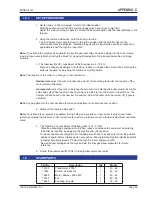
1. Set the cams on the air damper motor to the initial position.
Start the boiler and wait until the motor and gas valve have driven to high fire.
Adjust the main (primary) air gate to achieve the best combustion with the least buffeting in the
furnace.
2.
Using the low fire hold switch, hold the boiler in low fire.
The air damper motor should move to its low fire position and the high fire light on the
control panel should extinguish, indicating the gas and air input rates have been reduced to
approximately half the high fire input rate.
Note:
If gas flow rate equipment is available, the low fire gas input rate should be adjusted to the correct value
(see fuel input rates table) by rotating the black 1st stage partial adjustment ring located below the 2nd stage
solenoid.
3.
The ideal low fire CO
2
constituent of the flue gases is 8 - 10.5%.
Place an exhaust gas analyser into the flue, reduce or increase the amount of air entering the
boiler as required, by adjusting the low fire cam (N2) position.
Note:
The reaction of the motor to a change in cam positions is:
Reduced air:
adjust the cam to reduce the amount of air entering the boiler, the reaction of the
motor will be immediate.
Increased air:
adjust the cam to increase the amount of air entering the boiler, switch the low fire
hold switch off. When the motor has driven back to high fire turn the low fire hold switch on, the
damper will drive back to its new low fire position. Adjust the cams until the correct CO
2
figure is
achieved.
Note:
Any adjustment to the cam positions requires an adjustment to its interlock cam position.
4.
Switch off the low fire hold switch.
Note:
if gas flow rate equipment is available, the high fire gas input rate can now be set (see fuel input rates
table) by adjusting the pressure control screw located under a protective cover on the black electrical connection
block.
5.
The high fire CO
2
constituent of the flue gases is 10 - 10.5%.
Place an exhaust gas analyses into the flue, reduce or increase the amount of air entering
the boiler as required, by adjusting the high fire cam (N1) position.
To reduce the amount of high fire air, the damper will have to be driven to its low fire position
and back again, before it takes up its new position. Ensure that the high fire interlock cam N5
is always set approximately 5°
below the high fire motor position cam N1.
Record all cam settings and the high and low fire final gas elbow pressures for future
reference.
6. Adjust the pressure switch (PS2) to the high/low switch over point.
1.5
SPARE PARTS
Part No.
Description
Qty
Model
13195
Transformer, ZT931
1
40 - 60
11643
Switch, air pressure
1
40 - 60
14485
Motor, damper, A30 045Y
1
40 - 60
12075
Fan
1
40 - 60
14489
Coupling, air gate
1
40 - 60
Summary of Contents for J Series
Page 2: ...JGASUK IOMM 2015 2 Fulton Ltd Page II ...
Page 54: ...JGASUK IOMM 2015 2 Fulton Ltd Page 48 APPENDIX A ...
Page 58: ...JGASUK IOMM 2015 2 Fulton Ltd Page 52 APPENDIX A ...
Page 60: ...JGASUK IOMM 2015 2 Fulton Ltd Page 54 ...
Page 62: ...JGASUK IOMM 2015 2 Fulton Ltd Page 56 ...


