JGASUK-IOMM-2015-2
Fulton Ltd
Page 58
APPENDIX - C
1.3
ADDITIONAL CONTROLS
Low Fire Hold Switch -
Used to maintain the boiler in the low fire mode during commissioning.
1.4
COMMISSIONING
Model
6
8
10
15
20
30
40
50
60
Low Fire
m
3
/h
3.5
4.7
5.8
8.7
11.6 11.6 23.2 29.0 34.8
ft
3
/min.
2.1
2.8
3.4
5.1
6.9
10.3 13.7 17.1 20.5
High Fire
m
3
/h
7.0
9.3
11.6 17.4 23.2 34.8 46.4 58.1 69.6
ft
3
/min.
4.1
5.5
6.8
10.2 13.7 20.5 27.3 34.2 41.0
Note:
Boilers are pre-commissioned before leaving the factory to ensure optimum gas input rates and combustion
values.
1.4.1
FUEL INPUT RATES
Commissioning should be carried out by a qualified Fulton Service Engineer.
To achieve the ideal combustion efficiency and gas input rates, a gas flow rate meter is required
to measure the fuel input to the boiler.
1.4.2
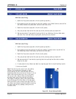
AIR DAMPER MOTOR - FACTORY CAM SETTINGS
Terminal
Position
Degrees
N1
High Fire Motor Cam
45°
N2
Low Fire Motor Cam
10°
N5
High Fire Interlock Cam
40°
N6
Low Fire Interlock Cam
15°
Blue cam N7 not used
Red cam
N6
Red cam
N5
Red cam N4 not used
Red cam N3 not used
Yellow cam
N2
Yellow cam
N1
Figure. 37 - Air Damper Motor
Note:
The high fire interlock cam should always be set approximately 5°
lower than the high fire cam position.
The low fire interlock cam should always be set approximately
5° higher than the low fire cam position.
Summary of Contents for J Series
Page 2: ...JGASUK IOMM 2015 2 Fulton Ltd Page II ...
Page 54: ...JGASUK IOMM 2015 2 Fulton Ltd Page 48 APPENDIX A ...
Page 58: ...JGASUK IOMM 2015 2 Fulton Ltd Page 52 APPENDIX A ...
Page 60: ...JGASUK IOMM 2015 2 Fulton Ltd Page 54 ...
Page 62: ...JGASUK IOMM 2015 2 Fulton Ltd Page 56 ...


