JGASUK-IOMM-2015-2
Fulton Ltd
Page 17
INSTALLATION - 2
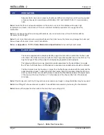
Gas input mounting flange location
Adjustable pressure switch
Input gas test point
Hydraulic brake
Main gas flow adjustment
High fire solenoid
Low fire flow adjustment
Test point 1 downstream (internal
leak test)
Test point 2 downstream
Test point 1upstream
Output pressure controller adjusting
screw
Operating pressure indicators
Figure. 16 -
40J - 60J Gas Valve (non modulating burner): Major Components
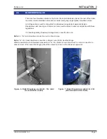
GAS ACTUATOR
GAS GOVERNOR & VALVE
Servo motor body
Valve coupling
Gas governor
Filter caps
Filter & main housing
Gas out flange
Gas valve
Electrical connections
Low gas pressure switch
Gas in flange
Figure. 17 -
30J - 60J Gas Valve (fully modulating burner): Major Components
Summary of Contents for J Series
Page 2: ...JGASUK IOMM 2015 2 Fulton Ltd Page II ...
Page 54: ...JGASUK IOMM 2015 2 Fulton Ltd Page 48 APPENDIX A ...
Page 58: ...JGASUK IOMM 2015 2 Fulton Ltd Page 52 APPENDIX A ...
Page 60: ...JGASUK IOMM 2015 2 Fulton Ltd Page 54 ...
Page 62: ...JGASUK IOMM 2015 2 Fulton Ltd Page 56 ...


