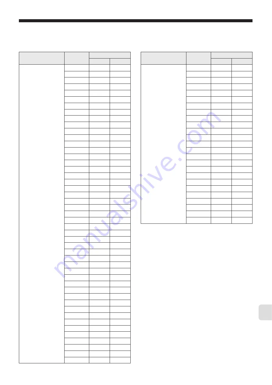
FujiFilm PXG4 Operation Manuals Download Page 136

– 135 –

14

Chapter

PID palette Ch 3

Sv1

dP05

0

P1

dP05

1

i1

dP05

2

d1

dP05

3

hyS1

dP05

4

CoL1

dP05

5

db1

dP05

6

bAL1

dP05

7

Ar1

dP05

8

rEv1

dP05

9

Sv2

dP05

10

P2

dP05

11

i2

dP05

12

d2

dP05

13

hyS2

dP05

14

CoL2

dP05

15

db2

dP06

0

bAL2

dP06

1

Ar2

dP06

2

rEv2

dP06

3

Sv3

dP06

4

P3

dP06

5

i3

dP06

6

d3

dP06

7

hYS3

dP06

8

CoL3

dP06

9

db3

dP06

10

bAL3

dP06

11

Ar3

dP06

12

rEv3

dP06

13

Sv4

dP06

14

P4

dP06

15

i4

dP07

0

d4

dP07

1

hyS4

dP07

2

CoL4

dP07

3

db4

dP07

4

bAL4

dP07

5

Ar4

dP07

6

rEv4

dP07

7

Sv5

dP07

8

P5

dP07

9

i5

dP07

10

d5

dP07

11

hyS5

dP07

12

CoL5

dP07

13

db5

dP07

14

Display Screen or

Channel

Parameter

dP

No.

Bit position

PID palette Ch 3

bAL5

dP07

15

Ar5

dP08

0

rEv5

dP08

1

Sv6

dP08

2

P6

dP08

3

i6

dP08

4

d6

dP08

5

hYS6

dP08

6

CoL6

dP08

7

db6

dP08

8

bAL6

dP08

9

Ar6

dP08

10

rEv6

dP08

11

Sv7

dP08

12

P7

dP08

13

i7

dP08

14

d7

dP08

15

hyS7

dP09

0

CoL7

dP09

1

db7

dP09

2

bAL7

dP09

3

Ar7

dP09

4

rEv7

dP09

5

SVMX

dP10

0

PL1M

dP10

1

Display Screen or

Channel

Parameter

dP

No.

Bit position

Summary of Contents for PXG4

Page 1: ...c...

Page 2: ...f the product may result in personal injury or damage to the product Ambient temperature 10 to 50 C Ambient humidity 90 RH or less non condensing Installation category 2 According to IEC 1010 1 Degree...

Page 3: ...ron particles in the air Locations where the controller is subject to interference from static electricity magnetism or noise Locations where the controller is exposed to direct sunlight Locations whe...

Page 4: ...output requires warm up time when the power is turned on Use a delay relay if the contact output signal is used for circuits such as the external interlock circuit Use a supplemental relay as the life...

Page 5: ...ormal Reverse Setting 37 Setting the Normal Reverse Setting 37 SV Lower Limits SV Upper Limits 38 Setting the SV Upper and Lower Limits 38 OUT1 Proportional Cycles OUT2 Proportional Cycles 39 Setting...

Page 6: ...Compensation 79 Remote SV Zero Adjustment Remote SV Span Adjustment 80 Adjusting Remote SV Zero Span 80 Remote SV Input Range 81 Setting the Remote SV Input Range 81 Remote SV Input Filter 82 Setting...

Page 7: ...s PFB Ch10 126 PFB Dead Band 127 Setting Valve Stroke Time 127 Valve Stroke Time 127 Setting the Valve Stroke Time 127 PFB Input Adjustment Command 128 Making Adjustments Manually 128 Making Adjustmen...

Page 8: ...0 to 20mA DC 4 to 20mA DC R Note 2 4 Re transmission output voltage 0 to 5V DC 1 to 5V DC 0 to 10V DC 2 to 10V DC S Note 2 4 7 Option 1 None Y RS485 M Digital input No 1 digital input No 2 T Digital...

Page 9: ...ion output voltage 0 to 5V DC 1 to 5V DC 0 to 10V DC 2 to 10V DC S Note 4 Transmitter power supply T Note 1 4 7 Option 1 None Y RS 485 M Digital input No 1 digital input No 2 T Digital input No 1 RSV1...

Page 10: ...9 1 Chapter Chapter 1 Part Names and Functions Part Names and Functions 10...

Page 11: ...tems in channel screen display and parameter screen display Key Pressing once will decrease the setting value by one Holding down the button will continue to decrease the value It changes SV on the PV...

Page 12: ...11 2 Chapter Chapter 2 Overview of Basic Operations and Parameters Basic Operation 12 Parameter Overview 14 Steps for Setting Parameters 19...

Page 13: ...ction outlines each mode and explains its key functions Refer to the following diagram for information about key functions and changing modes Press and hold means to press a key and hold it for about...

Page 14: ...ter monitor mode with MV1 selected Use the key and key to scroll through the information Monitor Mode Setup Mode Setup mode allows you to set the parameters for the device To enter setup mode first pr...

Page 15: ...alue Cannot be set 63 Ch 6 SET Setup Sets the parameters concerning input output 71 Ch 7 SyS System Sets the parameters concerning system definitions for the controller 89 Ch 8 ALM Alarm Sets the para...

Page 16: ...ysteresis Cooling proportional band coefficient Dead band Output convergence value Anti reset windup Normal reverse setting SV limit lower SV limit upper Selects the output limiter type Sets the maxim...

Page 17: ...setting Sbo1 Sbo2 FALT output 1 set value Ramp soak Step16 FLo1 FLo2 Soft start output 1 set value SFo1 Cold junction compensation Ao lower limit scaling Ao upper limit scaling PV input shift PV disp...

Page 18: ...time units System USER key allocation settings Ramp SV Decline Ramp SV effect no effect Ramp SV Incline Ramp SV slope time units Control methods Ramp SV SV display mode selection DI 1 function select...

Page 19: ...Display Display mask of each parameter dP01 dP30 Environmental Parameters Display timeout setting Remote blink setting Soft start blink setting ALM blink LED lamp flicker L C2 C2 lamp allocation Cont...

Page 20: ...rivationTime p 31 ON OFF Control Hysteresis p 32 SV Value Refer to SV Lower limit p 38 SV Upper limit p 38 2 Turn the power on Confirm that the connections are correct then turn on the power Immediate...

Page 21: ...20 MEMO 2 Chapter...

Page 22: ...rview of Operation Parameters Ch1 22 Auto Manual Switch 23 Standby Switch 24 Switching Between Local and Remote Operation 24 Ramp Soak Command 25 Auto tuning 25 DO Output Latch Cancel 26 SV No Switch...

Page 23: ...e 1 24 PrG PrG Ramp Soak Operation command Switches between ramp soak operation states oFF stop rUn run hLd hold oFF Displays End when finished and GS during guaranteed soak 25 AT AT Auto tuning runni...

Page 24: ...n 1 Press and hold the key The controller will switch from auto to manual 2 Use the keys to change the output value 3 Press and hold the key again to return to auto mode Refer to See USER Key Assignme...

Page 25: ...keys to display on when the lower part of the screen begins to blink 4 Press the key to confirm the setting Activate Standby Mode Control output DO and other outputs are turned off 5 Press the key to...

Page 26: ...peration mode Auto tuning Running auto tuning automatically sets the optimal PID Range oFF Stop Finish on Auto tuning normal type starts Lo Auto tuning low PV type starts There are two types of auto t...

Page 27: ...eviously set to a PID palette This allows SV to be changed easily Range Sv0 Sv1 Sv7 DI Set the ramp SV when changing the SV to reduce frequency of loss of control Changing SV Number Refer to See Ramp...

Page 28: ...return to the PV SV display of the operation mode Alarm Settings The following steps set the values for ALM1 to ALM5 when DO1 to DO5 are set as alarms Range 0 to 100 FS Setting Key Lock Refer to See C...

Page 29: ...hold the key to display the channel menu of the setting mode then use the keys to display o o o oP P P PE E E E C C C Ch h h h 1 1 1 1 Refer to See p 23 in this chapter for information on how to displ...

Page 30: ...e Time 31 ON OFF Control Hysteresis 32 Cooling Proportion Band Coefficient 33 Dead Band 34 Output Convergence Value 35 Anti reset Windup 36 Normal Reverse Setting 37 SV Lower Limits SV Upper Limits 38...

Page 31: ...t Setting 0 0 will turn the cooling into an on off control 0 0 to 100 0 1 0 Note 1 33 db db Dead band Shifts the set value for the cooling proportional band 50 to 50 0 Note 1 34 bAL bAL Output converg...

Page 32: ...In this situation adjust the output convergence value bAL Point Running auto tuning automatically sets PID See Auto Tuning p xx for more information The PID settings used during auto tuning are the o...

Page 33: ...row and PV and SV are nearly equal the output may frequently switch on and off Note that doing so may affect the operation life of the contact output PV ON OFF Control Output t SV SV HYS Set Value HYS...

Page 34: ...an be shifted with the db parameter Setting Cooling Proportional Band Cooling proportional band Proportional band P 2 x Coefficient Caution This setting is valid when there are dual outputs The standa...

Page 35: ...Band overlap band dead band MV output cooling heating MV MV 50 100 P 100 5 0 1 Press and hold the key to display the setup mode channel menu o o o oP P P PE E E E C C C Ch h h h 1 1 1 1 then use the...

Page 36: ...Press and hold the key to display the setup mode channel menu o o o oP P P PE E E E C C C Ch h h h 1 1 1 1 then use the keys to display Pid P P P Pi i i id d d d C C C Ch h h h 2 2 2 2 Refer to See p...

Page 37: ...e This range of integration is cut This range is integrated This range of integration is cut t AR value 1 Press and hold the key to display the setup mode channel menu o o o oP P P PE E E E C C C Ch h...

Page 38: ...alue Normal t 1 Press and hold the key to display the setup mode channel menu o o o oP P P PE E E E C C C Ch h h h 1 1 1 1 then use the keys to display Pid P P P Pi i i id d d d C C C Ch h h h 2 2 2 2...

Page 39: ...t lower limit SV upper limit PV input range SV lower limit upper limit lower limit 1 Press and hold the key to display the setup mode channel menu o o o oP P P PE E E E C C C Ch h h h 1 1 1 1 then use...

Page 40: ...ntroller use a short proportional cycle if the operating device is working properly Approx 1 sec to 2 sec Caution TC2 is only valid when there are dual outputs It cannot be set for current output or v...

Page 41: ...enu o o o oP P P PE E E E C C C Ch h h h 1 1 1 1 then use the keys to display Pid P P P Pi i i id d d d C C C Ch h h h 2 2 2 2 Refer to See p 31 in this chapter for information on how to display the c...

Page 42: ...t limit 13 limit 103 limit limit 14 3 limit limit limit 15 limit limit limit limit PHC PLC 103 output value before limiting PHC PLC limit no limit limit no limit 3 output value after limiting 1 Press...

Page 43: ...42 MEMO 4 Chapter...

Page 44: ...t Value 46 Proportional Band Integration Time Derivative Time 47 ON OFF Control Hysteresis 48 Cooling Proportional Band 48 Dead Band 49 Output Convergence Value 49 Anti reset Windup 50 Normal Reverse...

Page 45: ...oling proportional band 0 0 to 100 0 1 0 Note 2 48 db1 db1 Dead band 1 Sets the dead band 50 0 to 50 0 FS 0 Note 2 49 bAL1 bAL1 Output convergence value 1 Offset value added to the control output 100...

Page 46: ...0 0 Note 2 49 bAL7 bAL7 Output convergence value 7 Offset value added to the control output 100 0 to 100 0 0 50 single dual 49 Ar7 Ar7 Anti reset windup 7 Sets the anti reset windup 0 to 100 FS 100 FS...

Page 47: ...and hold the key to display m m m mv v v v1 1 1 1 The MV output of the monitoring mode is displayed 2 Press and hold the key to display the setup mode channel menu o o o oP P P PE E E E C C C Ch h h h...

Page 48: ...he normal reverse operations while using the PID selection function Do not switch between normal and reverse operation while controlling If PID No 1 SV No 1 increment function is executed under the PI...

Page 49: ...hysteresis is set to 3 0 C 4 Press the key to confirm the setting 5 Press the key to return to the operation mode PV SV display Cooling Proportional Band to Sets the cooling proportional band when du...

Page 50: ...rn to the operation mode PV SV display Output Convergence Value to Sets the output convergence value Up to seven types of output convergence value palettes 1 to 7 can be recorded Recorded output conve...

Page 51: ...ed Recorded normal reverse settings can be recalled from selected PID number P P P PL L L Ln n n n1 1 1 1 in the operation menu Setting the Normal Reverse Setting The following steps explain how to se...

Page 52: ...the key to confirm the setting 5 Press the key to return to the operation mode PV SV display Setting the Maximum PID Selection Number The following sets the maximum number that can be switched to when...

Page 53: ...52 MEMO 5 Chapter...

Page 54: ...ern 56 Ramp Soak Time Units 57 Ramp Soak SV Select step1 to step16 Ramp Time step1 to step16 Time Soak step1 to step16 58 Ramp Soak Mode 59 Guaranteed Soak Guaranteed Soak Lower Limit Guaranteed Soak...

Page 55: ...our min MM SS min sec hh MM 57 S S S Sv v v v 1 1 1 1 Sv 1 Ramp soak 1seg SV Set Value Sets the SV 0 to 100 FS 0 FS 58 T T T TM M M M1 1 1 1r r r r TM1r Ramp soak 1seg ramp time Sets the ramp time 00...

Page 56: ...ND Standby OFF Maintain Repeat On 14 P ON On END Standby OFF Standby Repeat Off 15 P ON On END Standby OFF Standby Repeat On 0 59 G G G Gs s s so o o ok k k k GSok Guaranty soak ON OFF Sets the guaran...

Page 57: ...ep4 step5 step6 step7 step8 step9 step10 step11 step12 step13 step14 step15 step16 Caution Do not change this parameter during ramp soak operations Make sure that PrG oFF before making changes 1 Press...

Page 58: ...o o oP P P PE E E E C C C Ch h h h 1 1 1 1 then use the keys to display PrG P P P PL L L LT T T T C C C Ch h h h 4 4 4 4 Refer to See p 56 in this chapter for information on how to display the operat...

Page 59: ...s SV step 1 ramp time TM1r step 1 soak time TM1s step 2 ramp time TM2r 100 200 50 SV TM1r TM1S TM3r TM3S t SV 2 SV h SV L SV 1 SV t program pattern PV SV 3 TM1r TM1S TM2r TM3r TM2S pattern with SV lim...

Page 60: ...on Maintain control Maintain control none 9 on Maintain control Maintain control on 10 on Maintain control Standby Mode none 11 on Maintain control Standby Mode on 12 on Standby Mode Maintain control...

Page 61: ...Ch h h h 1 1 1 1 then use the keys to display PrG P P P Pr r r rG G G G C C C Ch h h h 4 4 4 4 Refer to See p 56 in this chapter for information on how to display the operation menu 2 Press and hold...

Page 62: ...e power of the PXG turns off during operation due to power outage or other reasons this function can specify the ramp soak operation when the PXG turns on again The PXG returns to the state up to five...

Page 63: ...nnel menu o o o oP P P PE E E E C C C Ch h h h 1 1 1 1 then use the keys to display PrG P P P Pr r r rG G G G C C C Ch h h h 4 4 4 4 Refer to See p 56 in this chapter for information on how to display...

Page 64: ...eters Ch5 64 Ramp Soak Operation Display 65 Control Output Display 65 PFB Input Value Display 66 Remote SV RSV Input Display 66 Heater Current Display 67 Leak Current Display 67 Remaining Time on Time...

Page 65: ...control 3 0 to 103 0 Note 1 PFb PFb PFB Input Value Display Displays the input value of the position feedback 3 0 to 103 0 Note 2 66 rSv rSv RSV Input Value Display Displays the input value for RSV 5...

Page 66: ...h h 5 5 5 5 The monitor menu will appear 3 Press and hold the key then use the keys to display STAT S S S ST T T TA A A AT T T T Confirm the state of the ramp soak 4 Press the key to return to the op...

Page 67: ...nu 2 Press and hold the key then use the keys to display PFb P P P PF F F Fb b b b Confirm the motorized valve opening 3 Press the key to return to the operation mode PV SV display Remote SV RSV Input...

Page 68: ...keys to display CT1 C C C CT T T T1 1 1 1 Confirm the heater current value 3 Press the key to return to the operation mode PV SV display Leak Current Display Display the Leak current value Checking t...

Page 69: ...M2 to TM5 T T T TM M M M2 2 2 2 to T T T TM M M M5 5 5 5 4 Press the key to return to the operation mode PV SV display Error Source Display Displays the source of an error Checking the Error Source 1...

Page 70: ...o Check the palette No currently selected 3 Press the key to return to the operation mode PV SV display Current pattern No Displays the ramp soak pattern No currently selected Checking the Pattern No...

Page 71: ...70 MEMO 7 Chapter...

Page 72: ...y Zero Adjustment PV Display Span Adjustment 78 Cold Junction Compensation 79 Remote SV Zero Adjustment Remote SV Span Adjustment 80 Remote SV Input Range 81 Remote SV Input Filter 82 OUT1 Range OUT2...

Page 73: ...This is the procedure for specifying the units of the PV SV display C F C PvoF PvoF PV input shift Sets the amount of shift for PV input 0 to 100 FS 0 76 SvoF SVoF SV offset Sets the amount of shift i...

Page 74: ...1 during FALT 3 0 to 103 0 3 0 83 FLo2 FLo2 Output 2 set value during FALT Sets the output value for the control output OUT2 during FALT 3 0 to 103 0 3 0 Note 6 SFo1 SFo1 Soft start OUT1 set value Set...

Page 75: ...e the 250 resistor connected to the terminal block Or vice versa Different types of input thermocouple resistance thermometer bulb voltage or current input require different connections to the termina...

Page 76: ...each sensor can be set to exceed the possible measurement range but accuracy is not guaranteed in these cases PV input 1200 C 0 C 1000 C 200 C Possible range for setting upper lower limit Decimal Pla...

Page 77: ...0 C 95 C input SV Offset This function specifies the SV shift This is used to eliminate remaining offset when using P control Controls act on the calculated SV with SV offset Alarm determination acts...

Page 78: ...nge this unless absolutely necessary X Y control output input filter PID 100 63 input set value PV display t 5 sec 1 Press and hold the key to display the setup mode channel menu o o o oP P P PE E E E...

Page 79: ...Compensation p 79 for more information on changing these settings 2 Press and hold the key to display the setup mode channel menu o o o oP P P PE E E E C C C Ch h h h1 1 1 1 then use the keys to displ...

Page 80: ...tting Cold Junction Compensation 1 Press and hold the key to display the setup mode channel menu o o o oP P P PE E E E C C C Ch h h h1 1 1 1 then use the keys to display SET S S S SE E E ET T T T C C...

Page 81: ...P P PE E E E C C C Ch h h h 1 1 1 1 then use the keys to display SET S S S SE E E ET T T T C C C Ch h h h 6 6 6 6 Refer to See p 74 in this chapter for information on how to display the operation menu...

Page 82: ...n use the keys to display S S S SE E E ET T T T C C C Ch h h h 6 6 6 6 Refer to See p 74 in this chapter for information on how to display the operation menu 2 Press and hold the key then use the keys...

Page 83: ...absolutely necessary remote SV input Y control output input filter PID 100 63 input remote SV display t Approx 5 sec 1 Press and hold the key to display the setup mode channel menu o o o oP P P PE E...

Page 84: ...egins to blink The OUT1 range is set to 0mA to 20mA 4 Press the key to confirm the setting 5 Repeat steps 2 4 excluding pressing and holding the key to set FALT OUT2 6 Press the key to return to the o...

Page 85: ...During manual mode the manual output value has priority but soft start will continue to keep track of the set time period Caution The soft start function cannot be used when there are dual outputs Do...

Page 86: ...ion output alarm output and operation mode display in standby mode The following three settings are available AO Re transmission Output DO Digital Output PV SV display operation mode display These can...

Page 87: ...mode channel menu o o o oP P P PE E E E C C C Ch h h h 1 1 1 1 then use the keys to display SET S S S SE E E ET T T T C C C Ch h h h 6 6 6 6 Refer to See p 74 in this chapter for information on how to...

Page 88: ...g steps explain how to set AO limit scaling by using 80 to 80 as an example Caution Make sure to set the value of AoH greater than AoL re transmission output calculated value actual re transmission ou...

Page 89: ...88 MEMO 8 Chapter...

Page 90: ...tem Parameters Ch7 90 USER Key Assignments 93 DI Function Select 94 DO Event Type 96 DO Option Functions 98 Ramp SV ON OFF Ramp SV decline Ramp SV incline Ramp SV slope time unit 99 SV Display Mode 10...

Page 91: ...Latch cancel all 13 Latch cancel DO1 14 Latch cancel DO2 15 Latch cancel DO3 16 Latch cancel DO4 17 Latch cancel DO5 18 Start timer DO1 19 Start timer DO2 20 Start timer DO3 21 Start timer DO4 22 Sta...

Page 92: ...5 output 0 102 0 96 doP5 doP5 DO5 option function setting Assigns the four types of option functions in bit units 0000 1111 0000 98 rMP rMP ramp SV ON OFF Set the ramp SV ON OFF OFF ramp SV OFF ON ram...

Page 93: ...off and on again Note 6 The range of the parameters in the shaded area indicates the industrial values PrCS PrCS Control target Allows you to select the control target Srv1 servo control 1 Srv2 servo...

Page 94: ...tween ramp soak RUN HOLD 11 Do not set 12 Cancel all latches 13 DO1 latch cancel 14 DO2 latch cancel 15 DO3 latch cancel 16 DO4 latch cancel 17 DO5 latch cancel 18 DO1 timer start 19 DO2 timer start 2...

Page 95: ...DO5 2 2 2 26 6 6 6 SV No 1 When selecting SV No increases the SV No by 1 1 Level 2 2 2 27 7 7 7 SV No 2 When selecting SV No increases the SV No by 2 2 Level 2 2 2 28 8 8 8 SV No 4 When selecting SV...

Page 96: ...h h h h 7 7 7 7 Refer to See p 93 in this chapter for information on how to display the channel menu 2 Press and hold the key then use the keys to display di1 d d d di i i i1 1 1 1 3 Press the key the...

Page 97: ...Type Behavior diagram Upper lower limit Alarm 16 Upper lower limit absolute 17 Upper lower limit deviation 18 Upper limit absolute lower limit deviation 19 Upper limit deviation lower limit absolute 2...

Page 98: ...al 11th segment Time signal 12th segment Time signal 13th segment Time signal 14th segment Time signal 15th segment Time signal 16th segment Time signal 17th segment Time signal 18th segment Time sign...

Page 99: ...lied the hold function is reset when any of the following actions occur Change SV value Change alarm type Change alarm settings Cancel standby Turn power off and on Using them as alarms 1 to 31 1 Sett...

Page 100: ...apter for information on how to display the channel menu 2 Use the keys to display rMP r r r rM M M MP P P P 3 Press the key then use the keys to select on when the bottom part of the display begins t...

Page 101: ...the keys to display SYS S S S SY Y Y YS S S S C C C Ch h h h 7 7 7 7 Refer to See p 93 in this chapter for information on how to display the channel menu 2 Press and hold the key then use the keys to...

Page 102: ...PID calculation and controls proceed according to the previously set PID parameters PID parameters can be set manually or through auto tuning AT It is the most basic control in this equipment Fuzzy P...

Page 103: ...menu o o o oP P P PE E E E C C C Ch h h h 1 1 1 1 then use the keys to display SYS S S S SY Y Y YS S S S C C C Ch h h h 7 7 7 7 Refer to See p 93 in this chapter for information on how to display the...

Page 104: ...running for nine or more hours Point If a high degree of control is required select fuzzy control or PID2 control and activate auto tuning to set PID Caution The PID parameters after auto tuning has...

Page 105: ...C C C Ch h h h1 1 1 1 then use the keys to display SYS S S S SY Y Y YS S S S C C C Ch h h h 7 7 7 7 4 Press and hold the key then use the keys to display CTrL C C C CT T T Tr r r rL L L L 5 Press the...

Page 106: ...105 9 Chapter Behavior when control is lost Limit Cycle PV SV Time tuning MV control lost 100...

Page 107: ...set value control loop close close open PV 1 Press and hold the key to display the setup mode channel menu o o o oP P P PE E E E C C C Ch h h h1 1 1 1 then use the keys to display SYS S S S SY Y Y YS...

Page 108: ...ning a process that cannot accommodate large changes in PV do not use auto tuning Auto tuning is also not suitable for processes requiring rapid response to voltage or flow controls Restart auto tunin...

Page 109: ...s coming from the motorized valve Point Servo control 1 can control the motorized valve even without a valve opening signal from the motorized valve The motorized valve opening is estimated from a cal...

Page 110: ...or information on how to display the channel menu 2 Press and hold the key then use the keys to display TrvL T T T Tr r r rv v v vL L L L 3 Press the key then use the keys to select 50 when the bottom...

Page 111: ...Startup Mode Settings This function specifies the mode that the device starts up in when power is supplied Select from the following fore options Range AUTo Control output auto mode MAn Control output...

Page 112: ...iew of Alarm Parameters Ch8 112 Alarm Hysteresis Delay Time Delay Time Units 113 HB Alarm Set Value HB Alarm Hysteresis 114 Load short circuit alarm setting Load short circuit alarm hysteresis 116 Loo...

Page 113: ...sis Sets the hysteresis for alarm output 5 ON OFF 0 to 50 FS 1 C 113 dLY5 dLY5 ALM5 delay Sets the delay detecting for alarm output 5 0 to 9999 sec min 0 sec min dL5U dL5U ALM5 delay time units Sets t...

Page 114: ...set value alarm set value delay time hysteresis OFF ON AH input OFF ON AL OFF AH OFF ON AL input upper limit alarm lower limit alarm range alarm Hysteresis Hysteresis Hysteresis Hysteresis Operation m...

Page 115: ...trical furnace power AC100 to 240V 50 60Hz 5 6 11 12 3 4 35 36 PXG CT1 heater current ON OFF alarm output t heater break alarm set value set value hysteresis Point This is not used when the heater is...

Page 116: ...to display CT1 C C C CT T T T1 1 1 1 5 Reads the current through CT1 The heater break alarm threshold is set to 70 80 of the electric current 6 Display the setup mode channel menu o o o oP P P PE E E...

Page 117: ...splay ALM A A A AL L L LM M M M C C C Ch h h h8 8 8 8 Refer to See p 113 in this chapter for information on how to display the channel menu See USER Key Assignments for more about setting the USER key...

Page 118: ...the loop break detection alarm sounds before even before the loop break detection time period PV does not rise even if the control output rises ON OFF alarm output t set value loop break detection ra...

Page 119: ...118 MEMO 10 Chapter...

Page 120: ...119 11 Chapter Chapter 11 Communication Parameters Ch9 Overview of Communication Parameters Ch9 120 ST No Setting 122 Parity Setting 122 Communication Permission 123...

Page 121: ...RS 485 converter make sure to correctly connect the cable between the converter and master Communication will not occur properly if the connection is incorrect Also make sure to correctly set any comm...

Page 122: ...nication menu Ch9 includes the following items Note 1 Displays when the seventh digit of the model code is M V K J U or F Refer to See the Micro Controller Model PXG Communication Function Manual MODB...

Page 123: ...isplay Operation mode Parity Setting This is the procedure to specify communications speed and parity check Setting range Communications speed 9600 bps 19200 bps Parity check odd even none The combina...

Page 124: ...unication menu C C C Co o o oM M M M C C C Ch h h h 9 9 9 9 Refer to See p 122 in this chapter for information on how to display the channel menu 2 Press and hold the key to display the communication...

Page 125: ...124 MEMO 11 Chapter...

Page 126: ...125 12 Chapter Chapter 12 Position Feedback Parameters PFB Ch10 Overview of Position Feedback Parameters PFB Ch10 126 PFB Dead Band 127 Valve Stroke Time 127 PFB Input Adjustment Command 128...

Page 127: ...del code is V Display Parameter name Function Setting range Initial value Remarks Reference Page PGAP PGAP PFB dead band Sets PFB dead band 0 0 to 100 0 5 Note 1 127 TrvL TrvL Valve Stroke Time Sets t...

Page 128: ...signal on valve opening Hys PGAP 2 fixed valve closed signal on PGAP Hys Hys PGAP Operation mode Valve Stroke Time This function controls the time it takes for the motorized valve to go from fully op...

Page 129: ...channel menu 4 Press and hold the key then use the keys to select CAL C C C CA A A AL L L L Operation mode 5 Press the key then use the keys to select 1 when the bottom part of the display begins to b...

Page 130: ...ord those positions When 3 automatically changes back to 0 the adjustment is finished Automatic adjustment has failed if 10 or 20 are displayed 10 Over travel time 20 PFB span error 5 Press the key to...

Page 131: ...130 MEMO 12 Chapter...

Page 132: ...131 13 Chapter Chapter 13 Password Setup Ch11 Overview of Password Setup Ch11 132 Passwords 1 to 3 132...

Page 133: ...2 d d d dS S S SP P P P Display Mask for Each Parameters Ch13 C C C CF F F FG G G G Environmental Parameters Point The channel menu will not appear if the display mask function is set to not display H...

Page 134: ...133 14 Chapter Chapter 14 Display Mask for Each Parameter Ch12 Overview of Display Mask Ch12 134 Display Parameters 1 to 30 139...

Page 135: ...reen Pv dP30 14 SV dP30 13 Monitoring Screen FALT dP28 0 Mv1 dP28 1 Mv2 dP28 2 PFb dP28 3 rSv dP28 4 PASS dP28 Channel Display Screen oPEr dP29 0 Pid dP29 1 PLT dP29 2 PrG dP29 3 Mon dP29 4 SET dP29 5...

Page 136: ...P06 15 i4 dP07 0 d4 dP07 1 hyS4 dP07 2 CoL4 dP07 3 db4 dP07 4 bAL4 dP07 5 Ar4 dP07 6 rEv4 dP07 7 Sv5 dP07 8 P5 dP07 9 i5 dP07 10 d5 dP07 11 hyS5 dP07 12 CoL5 dP07 13 db5 dP07 14 Display Screen or Chan...

Page 137: ...v11 dP13 0 T11r dP13 1 T11S dP13 2 Sv12 dP13 3 T12r dP13 4 T12S dP13 5 Sv13 dP13 6 T13r dP13 7 T13S dP13 8 Sv14 dP13 9 T14r dP13 10 T14S dP13 11 Sv15 dP13 12 T15r dP13 13 T15S dP13 14 Display Screen o...

Page 138: ...UkEy dP19 0 di1 dP19 1 di2 dP19 2 di3 dP19 3 di4 dP19 4 di5 dP19 5 do1T dP19 6 do2T dP19 7 do3T dP19 8 do4T dP19 9 do5T dP19 10 doP1 dP19 11 doP2 dP19 12 doP3 dP19 13 doP4 dP19 14 doP5 dP19 15 rMP dP...

Page 139: ...3 PFB Ch 10 PGAP dP24 0 TrvL dP24 1 CAL dP24 3 Password Ch 11 PAS1 dP25 0 PAS2 dP25 1 PAS3 dP25 2 Config Ch 13 ToUT dP26 0 r Fk dP26 2 SoFk dP26 3 ALMF dP26 4 L C1 dP26 6 L C2 rST dP26 8 bCon dP26 9 P...

Page 140: ...0 0 15 14 13 8 12 0 0 0 1 11 10 9 1 8 1 1 1 0 7 6 5 E 4 0 0 0 0 3 2 1 0 0 1 0 0 0 15 14 13 8 12 0 1 0 1 11 10 9 5 8 1 1 1 0 7 6 5 E 4 0 0 0 0 3 2 1 0 0 Set corresponding bits to the parameters that sh...

Page 141: ...140 MEMO 14 Chapter...

Page 142: ...ft Start Blink Setting 144 ALM Blink 145 Burnout Control Selection 146 Ramp soak pattern order 147 C2 Lamp Allocation 148 Controller Reset 149 Refer to The parameters for Config Ch13 are not displayed...

Page 143: ...rol selection Sets whether to maintain or stop the control when the PV input burnout is detected on Continuous control oFF Stop control oFF 146 P P P PT T T Tn n n nT T T T PTnT Ramp soak pattern orde...

Page 144: ...setup mode hold down hold down hold down only during manual mode manual lamp ON change display only channel display Press several times parameter display 1 Press and hold the key to display n n n nv...

Page 145: ...o confirm the setting 5 Press the key to return to the operation mode PV SV display Soft Start Blink Setting This section explains how to specify whether S S S So o o oF F F FT T T T blinks in the SV...

Page 146: ...r information on how to display the channel menu 2 Press and hold the key then use the keys to select ALMF A A A AL L L LM M M MF F F F 3 Press the key then use the keys to select 7 when the bottom pa...

Page 147: ...ut PV value and the preset SV value Use stop control initial value unless otherwise required 1 Press and hold the key to display the setup mode channel menu o o o oP P P PE E E E C C C Ch h h h 1 1 1...

Page 148: ...9 to step 12 3 Step 13 to step 16 4 Step 1 to step 8 5 Step 9 to step 16 6 Step 1 to step 16 1 Press and hold the key to display the setup mode channel menu o o o oP P P PE E E E C C C Ch h h h 1 1 1...

Page 149: ...er than front SV is selected 9 during PID selection when PID other than Pid channel is selected 10 during auto tuning 1 Press and hold the key to display the setup mode channel menu o o o oP P P PE E...

Page 150: ...Ch h h h 1 1 1 1 then use the keys to display CFG C C C CF F F FG G G G C C C Ch h h h1 1 1 13 3 3 3 Refer to See p 143 in this chapter for information on how to display the channel menu 2 Press and h...

Page 151: ...150 MEMO 15 Chapter...

Page 152: ...151 16 Chapter Chapter 16 Troubleshooting Troubleshooting 152...

Page 153: ...e output settings during standby mode Ch6 Manual mode cannot be changed Manual mode is not assigned to the USER key Check the USER key assignments Ch7 The DI function is not set to manual mode Check t...

Page 154: ...153 17 Chapter Chapter 17 Appendix Delay Start Function 154 Return to Factory Default Setting Function 155...

Page 155: ...he following steps will explain how to assign the delay start to DI 2 Do2 and to set the delay time to 15 minutes For the detailed setting for each parameter see the setting procedure for each paramet...

Page 156: ...C Ch h h h1 1 1 11 1 1 1 2 Display P P P PA A A AS S S S1 1 1 1 and set FE01 F F F FE E E E0 0 0 01 1 1 1 3 Display P P P PA A A AS S S S2 2 2 2 and set FE02 F F F FE E E E0 0 0 02 2 2 2 4 Display P P...

Page 157: ...156 MEMO 17 Chapter...

Page 158: ...es Div Sales Group Gate City Ohsaki East Tower 11 2 Osaki 1 chome Shinagawa ku Tokyo 141 0032 Japan http www fujielectric com Phone 81 3 5435 7280 7281 Fax 81 3 5435 7425 http www fujielectric com pro...

Reviews: