


3-26
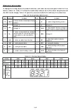
Table 3.17 Segment Display for I/O Signal Status in Hexadecimal Format
LED No.
LED4
LED3
LED2
LED1
Bit
15 14 13 12
11
10
9
8
7
6
5
4
3
2 1 0
Input
terminal
(RST)* (XR)*
(XF)*
- - - - - - - - X3
X2
X1
REV
FWD
Output
terminal
- - - - - - -
30AC
- - - - - - - Y1
Binary
0 0 0 0
0
0
0
0
0
0
0
0
0
1 0 1
Example
Hexa-
decimal
on the
LED
monitor
– : No corresponding control terminal exists.
* (XF), (XR), and (RST) are assigned for communication. Refer to "
Displaying control I/O signal terminals
under communication control
."
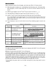
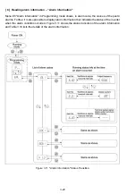
Displaying control I/O signal terminals under communication control
During control via communication, input commands sent via RS-485 communications cable can be
displayed in two ways: "display with ON/OFF of the LED segment" and "in hexadecimal format." The
content to be displayed is basically the same as that for the control I/O signal terminal status display;
however, (XF), (XR), and (RST) are added as inputs. Note that under communications control, I/O
display is in normal logic (using the original signals that are not inverted).
Refer to RS-485 Communication User's Manual for details on input commands sent through
RS-485 communications.
Summary of Contents for Frenic Mini FRN001C1E-2U
Page 85: ...5 4 ...
Page 88: ...5 7 ...
Page 89: ...5 8 C codes Control Functions of Frequency ...
Page 92: ...5 11 J codes Application Functions y codes Link Functions ...
Page 167: ...8 6 8 3 Common Specifications ...
Page 168: ...8 7 ...
Page 171: ...8 10 8 5 External Dimensions 8 5 1 Standard models ...
Page 172: ...8 11 ...
Page 173: ...8 12 8 5 2 Models available on order EMC filter built in type ...
Page 174: ...8 13 ...
Page 192: ...MEMO ...
Page 193: ...MEMO ...
Page 194: ...MEMO ...
Page 196: ...Fuji Electric FA Components Systems Co Ltd Fuji Electric Corp of America 2007 06 F07 F07 00CM ...