


3-1
Chapter 3 OPERATION USING THE KEYPAD
3.1 Keys, Potentiometer, and LED on the Keypad
As shown in the figure at right, the
keypad consists of a four-digit LED
monitor, a potentiometer (POT), and
six keys.
The keypad allows you to start and
stop the motor, monitor running
status, and switch to the menu mode.
In the menu mode, you may set the
function code data, monitor I/O signal
states, maintenance information, and
alarm information.
Table 3.1 Overview of Keypad Functions
Monitor,
Potentiometer
and Keys
Functions
Four-digit, 7-segment LED monitor which displays the following according to the
operation modes *.
In Running mode:
Running status information (e.g., output frequency,
current, and voltage)
In Programming mode: Menus, function codes and their data
In Alarm mode:
Alarm code, which identifies the error factor if the
protective function is activated.
Potentiometer (POT) which is used to manually set a reference frequency,
auxiliary frequencies 1 and 2 or PID process command.
RUN key. Press this key to run the motor.
STOP key. Press this key to stop the motor.
/
UP/DOWN keys. Press these keys to select the setting items and change the
function data displayed on the LED monitor.
Program/Reset key which switches the operation modes* of the inverter.
In Running mode:
Pressing this key switches the inverter to Program-
ming mode.
In Programming mode:
Pressing this key switches the inverter to Running
mode.
In Alarm mode:
Pressing this key after removing the error factor will
switch the inverter to Running mode.
Function/Data key which switches the operation you want to do in each mode as
follows:
In Running mode:
Pressing this key switches the information to be dis-
played concerning the status of the inverter (output
frequency (Hz), output current (A), output voltage (V),
etc.).
In Programming mode: Pressing this key displays the function code and sets
the data entered with the
and
keys or the POT.
In Alarm mode:
Pressing this key displays the details of the problem
indicated by the alarm code that has come up on the
LED monitor.
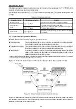
* FRENIC-Mini features three operation modes: Running, Programming, and Alarm. Refer to Section 3.2
"Overview of Operation Modes."
STOP key
Potentiometer
RUN key
LED monitor
Down key
Up key
Function/Data key
Program/Reset key
Summary of Contents for Frenic Mini FRN001C1E-2U
Page 85: ...5 4 ...
Page 88: ...5 7 ...
Page 89: ...5 8 C codes Control Functions of Frequency ...
Page 92: ...5 11 J codes Application Functions y codes Link Functions ...
Page 167: ...8 6 8 3 Common Specifications ...
Page 168: ...8 7 ...
Page 171: ...8 10 8 5 External Dimensions 8 5 1 Standard models ...
Page 172: ...8 11 ...
Page 173: ...8 12 8 5 2 Models available on order EMC filter built in type ...
Page 174: ...8 13 ...
Page 192: ...MEMO ...
Page 193: ...MEMO ...
Page 194: ...MEMO ...
Page 196: ...Fuji Electric FA Components Systems Co Ltd Fuji Electric Corp of America 2007 06 F07 F07 00CM ...