


3-24
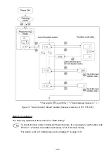
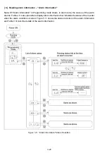
Basic key operation
Before checking the status of the I/O signals, set function code E52 to "2: Full-menu mode."
(1) When the inverter is powered on, it automatically enters Running mode. In Running mode,
press the
key to enter Programming mode. The menu for function selection will be dis-
played.
(2) With the menu displayed, use the
and
keys to select "I/O check" (
KAQ
).
(3) Press
the key to display the codes for the I/O check item list. (e.g.
A
)
(4) Use
the and
keys to select the desired I/O check item, then press the
key.
The corresponding I/O check data will appear. For control I/O signal terminal and control circuit
terminal input under communication control, use the
and
keys to select one of the two
different display methods.
(5) Press the key to return to the I/O check item list. Press the
key again to return to the
menu.
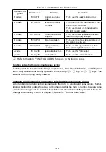
Table 3.15 I/O Check Items
LED monitor
shows:
Contents Description
A
I/O signals on the control
circuit terminals
Shows the ON/OFF state of the digital I/O terminals.
Refer to "
Displaying control I/O signal terminals
"
below for details on the display contents.
A
I/O signals on the control
circuit terminals under
communication control
Shows the ON/OFF state for the digital I/O terminals
that received a command via RS-485 communica-
tions. Refer to "
Displaying control I/O signal ter-
minals
" and "
Displaying control I/O signal termi-
nals under communication control
" below for de-
tails of the item displayed.
A
Input voltage on terminal [12]
Shows the input voltage on terminal [12] in volts (V).
A
Input current on terminal [C1]
Shows the input current on terminal [C1] in milliam-
peres (mA).
A
Output voltage to analog
meters [FMA]
Shows the output voltage on terminal [FMA] in volts
(V).
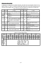
Displaying control I/O signal terminals
The status of control I/O signal terminal status may be displayed with ON/OFF of the LED segment
or in hexadecimal display.
Display I/O signal status with ON/OFF of the LED Segment
As shown in Table 3.16 and the figure below, each of the segments "a" to "e" on LED1 lights when
the corresponding digital input terminal ([FWD], [REV], [X1], [X2], or [X3]) is short-circuited with
terminal [CM] or [PLC]*, and does not light when it is open. Segment "a" on LED3 lights when the
circuit between output terminals [Y1] and [Y1E] is closed and does not light when the circuit is open.
Segment "a" on LED4 is for terminal [30ABC]. Segment "a" on LED4 lights when the circuit between
terminals [30C] and [30A] is short-circuited (ON) and does not light when it is open.
*Terminal [CM] if the jumper switch is set for SINK; terminal [PLC] if the jumper switch is set for
SOURCE.
Summary of Contents for Frenic Mini FRN001C1E-2U
Page 85: ...5 4 ...
Page 88: ...5 7 ...
Page 89: ...5 8 C codes Control Functions of Frequency ...
Page 92: ...5 11 J codes Application Functions y codes Link Functions ...
Page 167: ...8 6 8 3 Common Specifications ...
Page 168: ...8 7 ...
Page 171: ...8 10 8 5 External Dimensions 8 5 1 Standard models ...
Page 172: ...8 11 ...
Page 173: ...8 12 8 5 2 Models available on order EMC filter built in type ...
Page 174: ...8 13 ...
Page 192: ...MEMO ...
Page 193: ...MEMO ...
Page 194: ...MEMO ...
Page 196: ...Fuji Electric FA Components Systems Co Ltd Fuji Electric Corp of America 2007 06 F07 F07 00CM ...