RWB II ROTARY SCREW COMPRESSOR UNITS
MAINTENANCE
S70-200 IOM
Page 42
BARE COMPRESSOR MOUNTING
The following procedure is required only when a bare com-
pres sor is replaced in the fi eld.
1. Thoroughly clean the compressor feet and mounting pads
of burrs and other foreign matter to ensure fi rm seating of
the compressor.
2. Clean the discharge fl ange surfaces on the compres sor
and separator.
3. Install a gasket on the compressor discharge connec tion
of the separator.
4. Set the compressor on its base and tighten the dis charge
fl ange bolts. The feet of the compressor should lift off the
mounting base. If the compressor feet do not raise off
the mounting base install a thicker discharge gasket and
re in stall the discharge fl ange bolts. Check the clear ance
be tween the feet and the base with a feeler gauge. Shim the
compres sor feet (gauge reading plus .002").
5. Tighten compressor hold down bolts.
6. Complete compressor/motor coupling alignment (see
IN STAL LA TION section).
7. Complete tubing, piping and wiring per the P & I and wir-
ing diagrams.
SHUTDOWN DUE TO IMPROPER OIL
PRESSURE (HIGH STAGE and BOOSTER)
The compressor must not operate with incorrect oil
pres sure.
1. For units with Quantum Control Panels, refer to
CON TROL SETUP - "OIL SETPOINTS DISPLAY" in
S90-010 O.
2. For units with Microprocessor Control Panels, install a
pres sure transducer to monitor the pressure of the oil sup ply
to the balance piston. The correct pressure with the so le noid
closed is 50 psi below discharge pressure (+/-15 psi). The
correct pressure with the solenoid valve open is within 20 psi
of oil pressure as measured at the oil manifold.
At 60 psi and less differential pressures, with the solenoid
valve closed, the oil pressure should be 1.1 times suction
pressure (+/-15 psi). Differential pressure is defi ned as de-
fi ned as discharge pressure minus suction pressure.
The shutdown should occur if the condition persists for 2
minutes. For the fi rst 5 minutes after compressor start has
been confi rmed, this safety shutdown may be ignored.
3. For units with Electromechanical Control Panels, a safety
shutdown on balance piston oil pressure may be omitted.
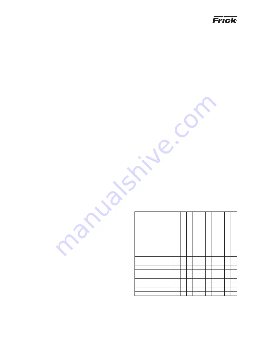
GREASE COMPATIBILITY
If it becomes necessary to mix greases, be careful not to
combine different oil bases or thickeners. DO NOT mix a
min er al oil-base grease with a synthetic oilbase grease.
Also, a grease with a lithium thickener should not be mixed
with one containing a sodium thickener. The table il lus trates
the com pat i bil i ty of various types of grease based on re sults
by Na tion al Lubricating Grease Institute (NLGI). The chart
in di cates a great variance in compaibility with the greases
tested.
Aluminum
Complex
– I I C I I I I C I
Barium
I – I C I I I I I I
Calcium
I I – C I C C B C I
Calcium
12-hydroxy
C C C – B C C C C I
Calcium
Complex
I I I B – I I I C C
Clay
I I C C I – I I I I
Lithium
I I C C I I – C C I
Lithium
12-hydroxy
I I B C I I C – C I
Lithium
Complex
C I C C C I C C – I
Polyurea*
I I I I C I I I I –
B = Borderline Compatibility
C = Compatible
I = Incompatible
* Standard
Alumin
um Comple
x
Bar
ium
Calcium
Calcium 12-h
ydro
xy
Calcium Comple
x*
Cla
y
Lithium
Lithium 12-h
ydro
xy
Lithium Comple
x
P
olyurea
NLGI Grease Compatibility Chart
Install the valve and adjust the spring ten sion ac cord ing ly
to main tain the pre de ter mined oil tem per a ture. The rec-
om mend ed oil temperatures are 130°F for ammonia and
140°F for R-22. Check with Frick ser vice for rec om mend ed
oil tem per a tures for other re frig er ants.
If all of the above steps have been properly per formed and
the desired oil temperature can not be achieved, con tact
Frick Service.


