RWB II ROTARY SCREW COMPRESSOR UNITS
INSTALLATION
S70-200 IOM
Page 12
ECONOMIZER - HIGH STAGE (OPTIONAL)
The economizer option provides an increase in system ca-
pac i ty and effi ciency by subcooling liquid from the con dens er
through a heat exchanger or fl ash tank before it goes to the
evapora tor. The subcooling is provided by fl ash ing liquid in
the economizer cooler to an intermediate pres sure level.The
intermediate pressure is provided by a port located part way
down the compres sion process on the screw compressor.
As the screw compressor unloads, the economizer port will
drop in pressure level, eventually being fully open to suc-
tion. Because of this, an output from the microproces sor
is gen er al ly used to turn off the supply of fl ashing liquid on
a shell and coil or DX economizer when the capacity falls
be low approximately 45%-60% capacity (85%-90% slide
valve po si tion). This is done because the compressor will
be more effi cient operating at a higher slide valve position
with the economizer turned off, than it will at a low slide valve
po si tion with the economizer turned on. Please note however
that shell and coil and DX economizers can be used at low
com pres sor capaciti es in cases where effi cien cy is not as
im por tant as assuring that the liquid supply is subcooled. In
such cases, the economi zer liquid solenoid can be left open
when ev er the com pressor is running.
WATER-COOLED OIL COOLING (Optional)
The plate and shell type water-cooled oil cooler is mount ed
on the unit complete with all oil piping. The cus tom er must
supply adequate water connections and install the two-way
water regulating valve if ordered in lieu of a three-way oil
temperature valve. It is recom mended (lo cal codes per mit ting)
that the water regula tor be installed on the water outlet con-
nec tion. Insert the water regulator valve bulb and well in the
cham ber pro vid ed on the oil outlet con nec tion. De ter mine
the size of the wa ter-cooled oil cool er sup plied with the unit,
then refer to ta ble for the water connec tion size. The water
supply must be suf fi cient to meet the re quired fl ow.
* Based on 100 foot liquid line. For longer runs, increase line
size accordingly.
** For models 60 and 76, contact Frick engineering.
LIQUID LINE SIZES/RECEIVER VOLUME
Liquid line sizes and the additional receiver volume (quanti-
ty of refrigerant required for 5 minutes of liquid injection oil
cooling) are given in the following table:
LIQUID LINE SIZE and RECEIVER VOLUME
LINE
SIZE*
POUND
LIQUID
RWB II
SCH 80
OD
PER
VOLUME
MODEL **
PIPE
TUBING
5 MIN.
CU FT
R-717
HIGH
STAGE*
100-134
3/4
–
80
2.0
177-270
1
–
140
4.0
316-480
1-1/4
–
250
7.0
R-717
BOOSTER*
100-134
1/2
–
20
0.5
177-270
3/4
–
30
1.0
316-480
1
–
40
1.5
R-22
HIGH
STAGE*
100-134
1-1/4
1-1/8
290
4.0
177-270
1-1/2
1-3/8
570
8.0
316-480
2
2-1/2
1,050
14.0
R-22
BOOSTER*
100-134
3/4
7/8
44
0.6
177-270
3/4 7/8 59 0.8
316-480
3/4 7/8 92 1.2
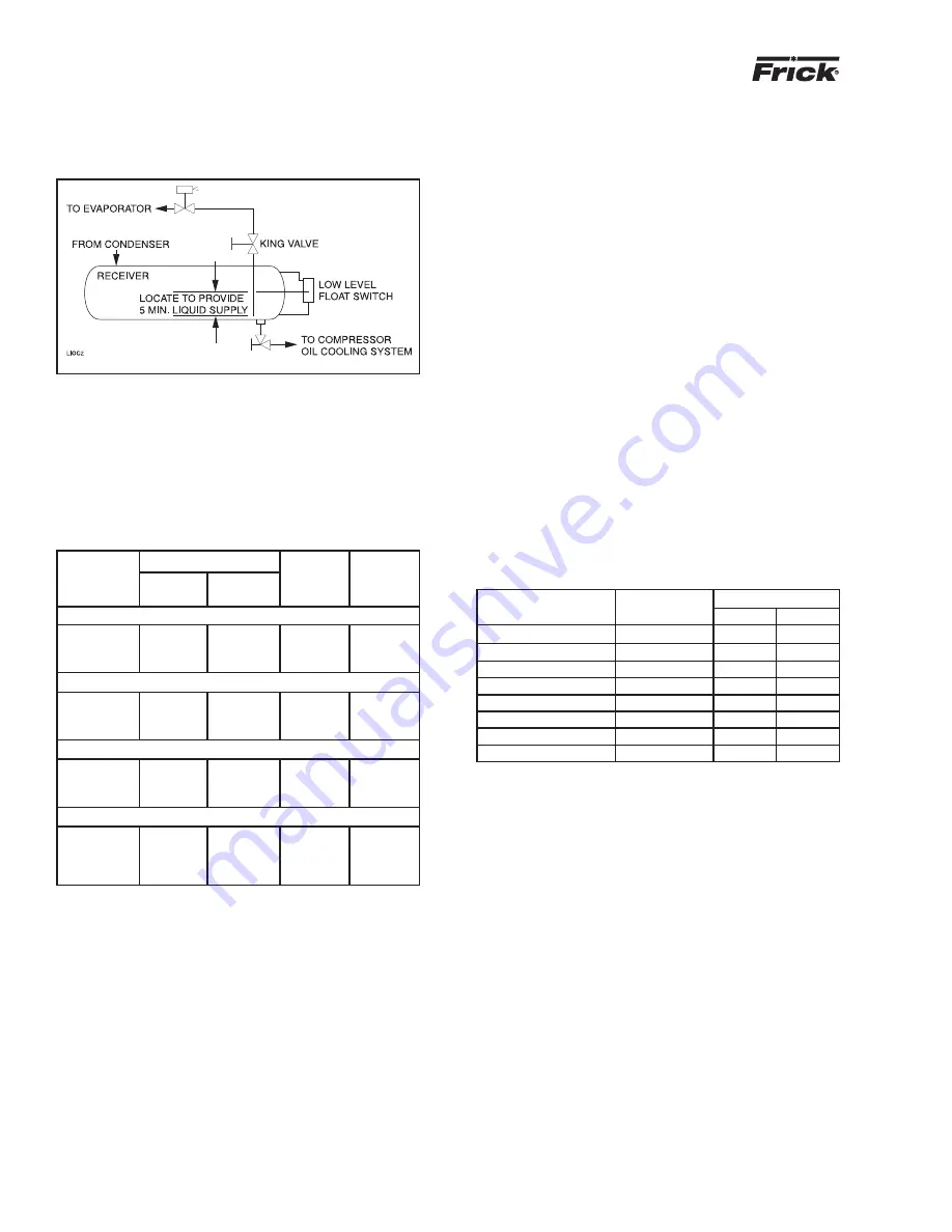
The level-control method utilizes a fl oat level control on the
receiver to close a solenoid valve feeding the evaporator
when the liquid falls below that amount necessary for 5
min utes of liquid injection oil cooling. See Figure 10.
Figure 10
Frick recommends a closed-loop system for the waterside
of the oil cooler. Careful at ten tion to water treatment is es-
sen tial to ensure adequate life of the cooler if cooling tower
wa ter is used. It is imperative that the condition of cool-
ing water and closed-loop fl uids be analyzed regularly
and as nec es sary and main tained at a pH of 7.4, but not
less than 6.0 for proper heat exchanger life. After initial
start-up of the compressor package, the strainer at the inlet
of the oil cooler should be cleaned several times in the fi rst
24 hours of op er a tion.
In some applications, the plate and shell oil cooler may be
subjected to severe water conditions, including high tem-
per a ture and/or hard water conditions. This causes ac cel -
er at ed scaling rates which will penalize the per for mance of
the heat exchanger. A chemical cleaning process will ex tend
the life of the Plate and Shell heat exchanger. It is im por tant
to es tab lish regular clean ing sched ules.
Cleaning: A 3% solution of Phosphoric or Oxalic Acid is
rec om mend ed. Oth er clean ing solutions can be ob tained from
your lo cal distributor, but they must be suitable for stain less
steel. The oil cooler may be cleaned in place by back fl ush ing
with recommended so lu tion for ap prox i mate ly 30 min utes.
After back fl ushing, rinse the heat exchanger with fresh water
to remove any re main ing clean ing so lu tion.
NOTE: The water-regulating valve shipped with the unit
will be sized to the specifi c fl ow for the unit.
OIL COOLER DATA TABLE
RWB
II
TYPICAL
CONNECTION
MODEL
COOLER
INLET
OUT
LET
60 - 134 High Stage
116 Plates
3"
3"
100 - 270 Booster
66 Plates
2"
2"
177/222 High Stage
190 Plates
3"
3"
270 High Stage
288 Plates
3"
4"
316/399 Booster
56 Plates
3"
3"
316/399 High Stage
136 Plates
4"
5"
480 Booster
72 Plates
3"
3"
480 High Stage
188 Plates
4"
5"


