


Foundry NetIron MLX Series Installation and Basic Configuration Guide
3-34
© 2008 Foundry Networks, Inc.
December 2008
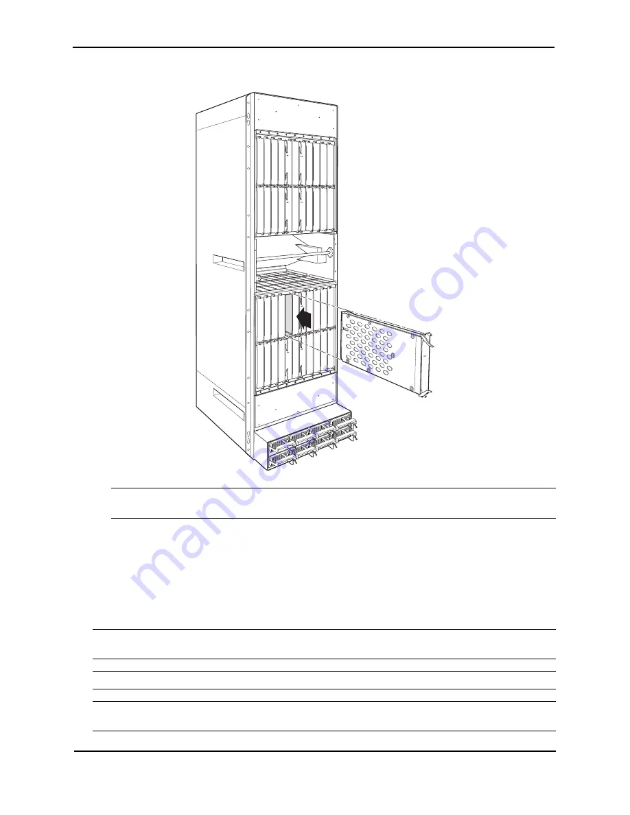
Figure 3.26 Installing a Module in a NetIron MLX-32 Chassis
NOTE:
The installation instructions for installing modules shown in the following illustrations are exactly the
same for interface, management, and switch fabric modules.
6.
Tighten the two screws at either end of the module front panel by pushing them in and turning them
clockwise. Then, tighten the screws further using the flat-head screwdriver.
NetIron MLX-32 Module Installation Details
The sequence for installing more than one card is important to ensure proper fit in the NetIron MLX-32 chassis.
When populating the NetIron MLX-32, start with the middle slot, and work towards the edge. Always fill the bottom
slots of the upper and lower card cage of the NetIron MLX-32 first. See “ NetIron MLX-32 Chassis” on page 2-5
for slot locations.
NOTE:
Do not insert interface modules running releases below 02.3.00 into slots 17 to 32 of a NetIron MLX-32
chassis. They should only be inserted into slots 1 to 16.
NOTE:
Any empty slots must contain slot blanks to ensure proper air flow within the chassis.
NOTE:
During the initially installation of the modules into a NetIron MLX 3200, Foundry recommends inserting
all the modules into the appropriate chassis slots before tightening the screws into the chassis.
Pw
r
Ac
tiv
e
Pw
r
Ac
tiv
e
Pw
r
Ac
tiv
e
Pw
r
Ac
tiv
e
Pw
r
Ac
tiv
e
Pw
r
Ac
tiv
e
Pw
r
Ac
tiv
e
Pw
r
Ac
tiv
e
Pw
r
Ac
tiv
e


