


Maintaining a NetIron MLX Series Router
December 2008
© 2008 Foundry Networks, Inc.
6-15
WARNING:
The NetIron MLX-32 fan assembly is heavy and will be off-balance as you remove it. Use both hands
on the handle.
WARNING:
Be careful not to insert your fingers into the fan while removing it from the chassis. The fan may still
be spinning at a high speed.
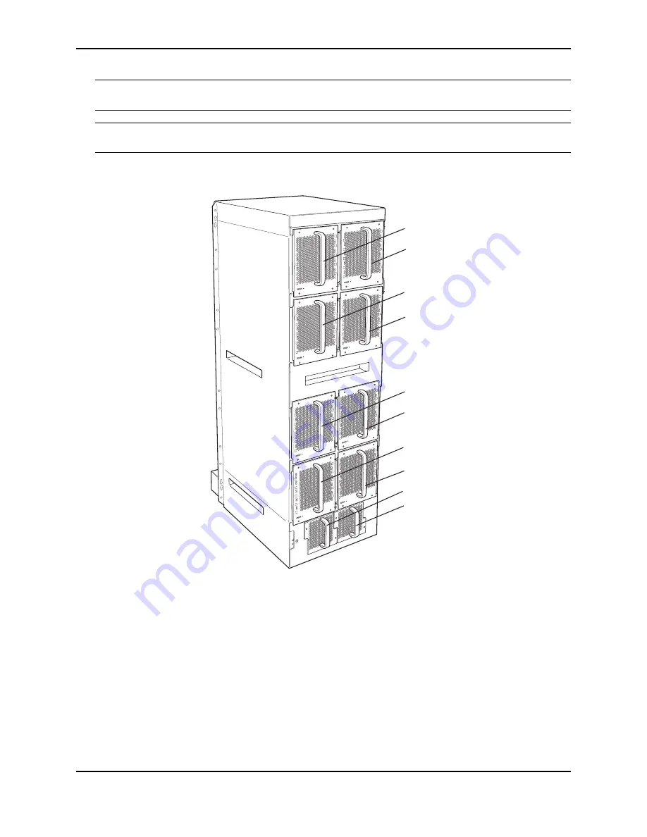
Figure 6.7 Removing a NetIron MLX-32 Fan
4.
Insert the new fan assembly into the fan slot and push the assembly in until the face plate is flush with the
chassis. Pushing the fan assembly in seats the fan connector with the chassis connector.
5.
Secure the fan assembly to the chassis by replacing and tightening the four screws on the upper-eight fan
assemblies and the two screws on the lower-two fan assemblies.
6.
Check the fan status LED in the lower left corner of the face plate. It will be red momentarily when power is
applied, then change to green when the fan comes up to speed.
7.
Access the CLI, and enter the
show chassis
command to verify that the fan is operating normally.
Replacing Fan Assemblies in the NetIron MLX-16
The NetIron MLX-16 has three fan assemblies: one accessible from the front of the chassis and two accessible
from the rear. The front assembly pushes air into the chassis and the rear fans pull air out.
Fan Module 1
Fan Module 2
Fan Module 6
Fan Module 8
Fan Module 10
Fan Module 4
Fan Module 3
Fan Module 5
Fan Module 7
Fan Module 9


