


Operation Maintenance Manual
2018-05
PN 9GV73109 - Revision: 02
Safety Spinning Wrench
43
C
O
M
M
IS
SION
IN
G
/
O
PE
R
A
TION
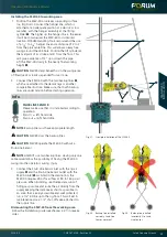
1. Take hose assembly
q
and unpack it.
2. Take the end with the female claw coupling
w
.
3. Press the female claw coupling from the hose supply
w
and the counterpart, the male claw coupling (3) at
the SSW-40, together.
4. Rotate both ends clockwise, until further turn is
impossible.
5. The Connection is now ready for operation and sealed.
Fig. 30: SSW-40 supply hose with swivel joint
Reverse in opposite order to loosen the connection.
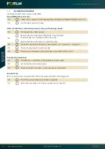
Perform following function tests:
1. Remedy all defects noted during checks.
CAUTION
Never attempt to start up when defective.
2. Activate pneumatic system.
3. Spin clockwise and counterclockwise.
• Do both roller assembly rotate in the same direction?
• Do the roller assemblies spin smoothly?
• Are there any noises or vibrations during spinning
operation, which may indicate damages to the bearings
or gearings?
4. Ensure that required operating data is observed:
Operating pressure (Air)
90 to 160 Psi
(6,2 to 11,03 bar)
4.1.2
Connecting Pneumatic System
Ensure that only personnel trained
for such work and conscious of the
risks involved perform work on the
pneumatic system.
WEAR EYE PROTECTION!
WEAR PROTECTIVE GLOVES!
Info
During installation, when setting up and taking
down as well as during operation of the SSW-40
ensure that the pneumatic lines do not chafe.
If necessary provide pneumatic lines with chafe
guard.
Info
Bleeding
The pneumatic system in the SSW-40 is bled
at the factory. Ensure that the rig's own supply
connections are bled before connecting the
SSW-40.
Info
Pre-Adjustment
The pneumatic system of the SSW-40 is adjusted
at the factory.
w
e
q