background image


43

7.  Apply Taylor HP Lubricant to the two syrup 

port o-rings and then place them into their 
respective places inside the syrup port.  A 
small tool may be used to ensure the         
o-rings are fully seated in the grooves.   
(See Figure 107.)   


26021


Figure 107


NOTE:  

O-RINGS MUST BE COMPLETELY 

SEATED TO PREVENT LEAKAGE.


Miscellaneous Cleaning Procedures 
 

The following cleaning procedures do not need 
to be performed on a daily basis.  Inspect these 
areas periodically and clean when necessary 
according to instructions. 


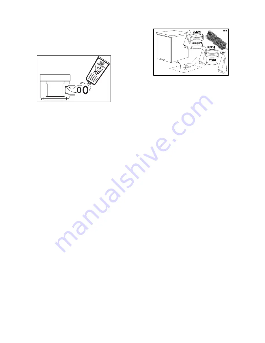
Cleaning the Area Under the Cabinet  


Figure 108 


1.  Prepare detergent water by mixing 

McD 

ALL PURPOSE SUPER CONCENTRATE 
(APSC) (HCS)

 with warm water according 

to manufacturer’s instructions. 


NOTE:  

DO NOT USE AN EXCESSIVE 

AMOUNT OF WATER OR DETERGENT IN 
CLEANING THE OUTSIDE OF THE CABINET.


2.  Carefully move the cabinet to an area 

outside of where it was sitting.   

 
3.  Clean the area using a single service towel 

moistened with warm detergent water.  Use 
a Large Brush if necessary. 

 
4.  Rinse area with a single service towel and 

clean, warm water and then wipe dry with a 
dry single service towel. 

 
5.  Clean the outside and underside of the 

cabinet using detergent, water and single 
service towels. 

 
6.  Carefully return the cabinet to its original 

place.   


Summary of Contents for FB 80M Series

Page 1: ...warranty form is provided with every FB 80M system located inside the FB 80M unit with this manual It is important that the operator carefully review the warranty and installation documents accompanyi...

Page 2: ......

Page 3: ...cleaned daily to ensure the highest standard of sanitation When your equipment is delivered or if it has been unused for more than 24 hours follow the DAILY OPENING PROCEDURES Always follow these saf...

Page 4: ...mental capabilities or lack of experience and knowledge if they have been given supervision or instruction concerning use of the appliance in a safe way and understand the hazards involved NOTE Childr...

Page 5: ...___________________________ _____________________________________ _____________________________________ _____________________________________ _____________________________________ ____________________...

Page 6: ...flavor lines to side of freezer 8 N A OUTER CABINET ASSEMBLY 1 Houses inner cabinet assembly 9 063179 TRAY FLAVORING FLAVOR BURST 8 Houses syrup bags 10 N A INNER CABINET ASSEMBLY 1 Houses syrup trays...

Page 7: ...5 General System Overview 26000 13 2 1 3 5 6 15 14 10 8 11 12 9 7 17 16 4 Figure 1...

Page 8: ...ip for opening front panel 6 068120 8 32 X 1 2 PAN HEAD SCREW 2 Fastens handle to front door panel 7 063258 BUMPER RUBBER W WASHER 4 Provides spacing between cabinet base and table 8 N A 10 32 X 1 2 P...

Page 9: ...7 Outer Cabinet 3 1 2 12 10 7 13 4 5 9 8 6 11 26001 Figure 2...

Page 10: ...zer when attached 9 063188 PANEL BASE FLAVOR BURST 1 Attaches the bottom of the inner and side panels 10 063185 PANEL RIGHT RACK SYRUP FLVR BRST 1 Holds outer syrup rails 11 068121 8 32 X 1 4 PAN HEAD...

Page 11: ...9 Inner Cabinet 26002 15 11 13 16 14 11 12 1 9 2 6 6 11 18 19 16 4 5 8 3 4 17 11 10 7 Figure 3...

Page 12: ...Supplies syrup to Injector Head from pumps 4A 063213 EYELET ROLLED FLANGE FB80 18 Provides tension in syrup line to affix to line coupler 4B 063253 COUPLING LINE FB80 2 Holds flavor lines in place 4C...

Page 13: ...B BRKT MTG ACCESSORY 1 Secures Mounting Bracket to Gear Box 11 063250 BRACKET HANGING ACCESSORY 1 Stores flavor line and Injector Drive Motor when not in use 12 063348 2 SURFACE RACEWAY 1 Attaches fla...

Page 14: ...ea Carries syrup from syrup bag to pump 2C 063284 TUBE SILICONE 188X 375 PE FB80 1 ea Connects barb fitment to tube port 2D 063224 FITTING 1 4X1 4 BARB FB80 1 ea Connects syrup tube to silicone tube...

Page 15: ...13 Syrup Pump and Related Parts 26004 11 3 10 9A 9B 9 4 5 6 8 7 9C 2 2A 2C 2D 2B 1 1D 1C 1A 1G 1B 1E 1F Figure 5...

Page 16: ...10C 063279 TUBE CLEAR PER FOOT FB80 5 Transports sanitizer to sanitizer flush 10D 063222 FITTING Y 44 FLAVOR BURST 2 Splits sanitizer flush tube into two 11 N A 6 9 TUBE ASSEMBLY TUBES 9 Transports s...

Page 17: ...15 Sanitizer Pump and Related Parts 26005 1 2 2 9 13 12 11 8 3 4 5 6 7 15 14 14G 14B 14E 14C 14F 14A 14D 13 13 14H 14H 14H 14H 10 10C 10A 10B 10C 10C 10D 10D 10C 10B 10C Figure 6...

Page 18: ...s to freezer to mount Keypad Bracket 4B 063240 BRACKET MOUNT KEYPAD FB80 1 Holds Keypad in place 4C 063212 KNOB BRKT MTG ACCESSORY 2 Fastens Keypad Bracket to mounting plate 5 N A REMOTE MICROPROCESSO...

Page 19: ...17 Remote Module and Electronic Parts 4A 4 4B 4C 1 2 3 5 5 6 7 8 26006 REVERSE SIDE 9 10 Figure 7...

Page 20: ...T ADAPTOR 840X1 06 1 Provides sealed cavity inside Adapter 2E 063262 ADAPTOR O RING PARKER 2 1 Creates tension to secure Adapter to freezer door 2F 063257 GASKET CONN TUBE 9 POS 1 Provides sealed cavi...

Page 21: ...19 Maintenance Kit and Spare Parts Kit 1 2 1D 2I 2C 1A 2A 2B 2D 2E 2F 2H 2K 2J 2L 1C 1B 2M 2G 2O 2N 26007 Figure 8...

Page 22: ...20...

Page 23: ...sanitizer each morning and to use the ROTOR FLUSH periodically to flush and sanitize the Injector Head while it is attached to the freezer door Sanitizing the Injector System 1 Prepare detergent wate...

Page 24: ...sanitary tray Spray the 9 Tube Assembly Manifold opening with McD Sanitizer HCS and allow it to sanitize for at least 5 minutes See Figure 14 26068 Figure 14 8 Hang the 9 Tube assembly on the Accesso...

Page 25: ...Figure 18 3 Insert the Drive Motor into the Drive Assembly Gear Box so that all four locking screws are seated properly and rotate the Motor counter clockwise to secure See Figure 19 26025 Figure 19...

Page 26: ...rs are installed and that none of the flavor bags are empty Replace flavors according to instructions if necessary 3 Ensure that the flavor level and the multi flavored timing are set to a desired lev...

Page 27: ...With a container under the dispensing spout press the ROTOR FLUSH key on the Keypad to purge any remaining product from the Injector Head See Figure 26 26250 Figure 26 2 Rotate the 9 Tube Assembly co...

Page 28: ...See Figure 34 Figure 34 Sanitizing the Injector System 1 Prepare detergent water by mixing McD ALL PURPOSE SUPER CONCENTRATE APSC HCS with warm water according to manufacturer s instructions Also prep...

Page 29: ...sary the Mounting Bracket may be removed and cleaned according to instructions in the SCHEDULED MAINTENANCE section See Figure 38 Figure 38 NOTE UNDER NORMAL OPERATING CONDITIONS IT IS NOT RECOMMENDED...

Page 30: ...n water and single service towels See Figure 43 Figure 43 11 The following do not need to be sanitized on a daily basis However inspect these areas and if necessary clean according to instructions in...

Page 31: ...turer s instructions Also prepare McD Sanitizer HCS solution according to manufacturer s instructions 2 Complete CIP Phase 2 of the Clean In Place procedure in the SCHEDULED MAINTENANCE section for th...

Page 32: ...llow the bag to settle in the tray See Figure 50 Figure 50 9 Make sure the syrup bag is settled neatly into the tray and then install the loaded tray into the cabinet See Figure 51 26196 Figure 51 10...

Page 33: ...of the corresponding syrup flavor 16 Place a container under the Injector Head to catch residual sanitizer solution and or fresh product to be dispensed and press PUMP FLUSH to prime the syrup line S...

Page 34: ...32...

Page 35: ...e Super Concentrate APSC HCS and McD Sanitizer HCS are recommended This Clean In Place procedure is detailed in 3 phases 1 9 Tube Assembly Cleaning 2 Syrup System Cleaning and 3 Reassembly To ensure m...

Page 36: ...oupler Body and then place them in McD Sanitizer HCS Allow these items to soak throughout the upcoming processes See Figure 64 26174 Figure 64 CIP Phase 2 Syrup System Cleaning NOTE THE FOLLOWING CLEA...

Page 37: ...over the container See Figure 68 26278 Figure 68 12 Gravity allows the sanitizer solution to flow through the adapter See Figure 69 26274 Figure 69 13 Allow the sanitizer solution to flow for at leas...

Page 38: ...you wish to flush 20 Touch the PUMP FLUSH key on the Keypad to start the Pump Flush procedure for the selected syrup line and proceed to Step 21 NOTE PUMP FLUSH WILL CONTINUE FOR 15 MINUTES YOU MAY CA...

Page 39: ...26277 Figure 78 26 Reconnect the Syrup Bag Connectors to the Syrup Bag Adapters See Figure 79 26275 Figure 79 27 Remove the Syrup Line Manifold the Duckbill Check Valve and Coupler Body from the sanit...

Page 40: ...stem as instructed in the following section Priming the Syrup System Priming the Syrup System Priming the syrups is necessary when first installing the flavors after the Clean In Place procedure when...

Page 41: ...e supply of fresh sanitizer solution in the Sanitizer Tank at all times The Sanitizer Tank should be checked on a daily basis and refilled if the supply is low Replace the sanitizer solution with a fr...

Page 42: ...ed Therefore clean only as needed or when disassembling the freezer door for cleaning at least once every 2 weeks Replacement o rings and gasket are available in the Spare Parts Kit NOTE THE TAYLOR 06...

Page 43: ...ee Figure 99 26096 Figure 99 7 Lubricate the black o rings with Taylor HP Lubricant and install them with the white gasket in their respective positions on the Injector Adapter See Figure 100 Figure 1...

Page 44: ...l tool may be needed to remove the o rings in the syrup line opening See Figure 102 Figure 102 3 Brush and clean all exposed surfaces of the Injector Head with detergent water and Small Brush Use the...

Page 45: ...rea Under the Cabinet Figure 108 1 Prepare detergent water by mixing McD ALL PURPOSE SUPER CONCENTRATE APSC HCS with warm water according to manufacturer s instructions NOTE DO NOT USE AN EXCESSIVE AM...

Page 46: ...the trays if necessary using detergent water and single service towels Also clean and sanitize the Syrup Bag Connectors according to instructions in the Clean In Place procedure in the SCHEDULED MAINT...

Page 47: ...m the sanitizer solution and place them on the drain tray to dry 6 Reassemble and reinstall the Mounting Bracket as directed in EQUIPMENT SETUP Cleaning the Accessory Hanging Bracket and 9 Tube Assemb...

Page 48: ...towel moistened with clean warm water and then wipe dry with a dry single service towel Keep water and detergent away from the cord and plug 5 Dry with a dry single service towel and install according...

Page 49: ...115 3 Empty all the sanitizer solution from the Sanitizer Tank See Figure 116 Figure 116 4 Repeat Steps 18 20 and Step 22 of the Clean In Place Procedure without sanitizer solution in the tank until...

Page 50: ...48...

Page 51: ...with a Taylor 063177 standard Adapter common to most freezers and a Taylor 063178 alternate Adapter for use with most Taylor Crown Series freezers However if these Adapters do not fit the freezer spo...

Page 52: ...M system ships with a standard Spigot Switch Assembly common to most freezers with flat handle bars Should your freezer have a round handle rod or a handle of unusual size or shape this standard switc...

Page 53: ...ned inside the 9 Tube Assembly Casing If your freezer includes an internal switch see description in previous section it is advised the Keypad assembly Injector Assembly and 9 Tube Assembly be install...

Page 54: ...ector Assembly 1 Remove the small screw on the back panel of the Cabinet and remove the panel See Figure 131 Figure 131 2 Locate the 9 Tube Lead Remove the dust cap and slide the coupler casing down S...

Page 55: ...these clean in place functions keep an adequate supply of fresh sanitizer solution in the Sanitizer Tank at all times The Sanitizer Tank should be checked on a daily basis but only needs to be refille...

Page 56: ...the Injector Assembly is already assembled disassemble each part according to instructions in the DAILY CLOSING PROCEDURES 1 Prepare detergent water by mixing McD ALL PURPOSE SUPER CONCENTRATE APSC HC...

Page 57: ...tate the Motor counter clockwise to secure See Figure 150 26025 Figure 150 Installing the Injector System and Mounting Bracket The Mounting Bracket helps stabilize the Injector Assembly on the freezer...

Page 58: ...R BRACKET AND THE BRACKET BASE NOTE THE BRACKET THUMB SCREW SHOULD ALWAYS BE INSERTED THROUGH THE UPPER BRACKET FIRST AND THEN SCREWED INTO THE BRACKET BASE PLACING IT ON THE OUTSIDE OF THE BRACKET AS...

Page 59: ...ed on the side of the freezer so that it is level horizontally It should be mounted at the same height as the Injector Assembly so that the syrup lines are level with the connection at the Injector He...

Page 60: ...hes or more above the 9 Tube Assembly Casing This will allow enough room for the Drive Motor to hang properly 1 Prepare detergent water by mixing McD ALL PURPOSE SUPER CONCENTRATE APSC HCS with warm w...

Page 61: ...cated on the Remote Microprocessor Module The Module can be placed according to preference with the 6 extension cord attached to the lower back of the cabinet Once connected to the Cabinet and turned...

Page 62: ...71 Figure 171 5 Connect the power cord to the port on the Module See Figure 172 Figure 172 6 Plug the power cord into an appropriate outlet 7 Activate the unit using the power switch next to the power...

Page 63: ...as previous flavors are emptied However you may change flavors periodically as desired 1 Prepare detergent water by mixing McD ALL PURPOSE SUPER CONCENTRATE APSC HCS with warm water according to manu...

Page 64: ...ure 181 26271 Figure 181 10 Attach the Syrup Bag Adapter to the bag fitment The notch of the black collar must settle into one of the grooves on the fitment in order to secure the connection See Figur...

Page 65: ...to complete the procedure NOTE THE PUMP FLUSH FUNCTION WILL AUTOMATICALLY SHUT OFF AFTER 15 MINUTES NOTE YOU MAY WANT TO PROCEED WITH STEP 16 WHILE THE PUMP FLUSH FUNCTION IS RUNNING AS TIME ALLOWS 1...

Page 66: ...64...

Page 67: ...MP FLUSH After selecting a particular pump by pressing a key 1 8 press and release this key to activate that particular syrup pump If the Syrup Bag Connector for that particular pump is connected to a...

Page 68: ...section Accessing Serving Count to use this feature NO SYRUP FLOW PRE PRIME PUMP PRIME PUMP Not applicable to this model SYRUP PUMP MALFUNCTION CHECK PUMP Not applicable to this model CHECK SANIT SUPP...

Page 69: ...le serving and draw the product as usual The flavors will dispense in one smooth motion changing in the order selected resulting in layers of flavors If no flavoring is desired i e to draw vanilla sim...

Page 70: ...el is most appropriate for your operation Fortunately the Flavor Burst system is adjustable for both flow and taste and may be quickly adjusted at any time between servings 1 Follow the freezer manufa...

Page 71: ...Touch and hold the MANUAL PRIME PUMP key on the Keypad until the Syrup Output bar graph flashes Approximately 5 seconds 2 Adjust the level indicated on the flashing bar graph by touching the INCREASE...

Page 72: ...70...

Page 73: ...of Remote Module Power Cord is disconnected from power source outlet Keypad Cable is disconnected from receptacle on the Remote Module The power fuse in the power entry module is blown The Pump Cable...

Page 74: ...ed The Switch stereo plug and Keypad jack are unplugged or not fully engaged The Spigot Switch is faulty The Keypad switch cable is faulty If an integrated switch is used the switch lever is not activ...

Page 75: ...to instructions Replace the items Always keep replacements in the Spare Parts Kit Call for service or replace the Adapter Probable Cause The Switch stereo plug and Keypad jack are unplugged or not fu...

Page 76: ...center Replace the 9 Tube Assembly Probable Cause The Injector Head is not properly installed onto the Injector Adapter The lower black o ring is not present on the outside of the Injector Adapter The...

Page 77: ...s faulty The Sanitizer Tank is empty One or more of the water line connections are not fully engaged and therefore allowing air intake while the pump is operating The sanitizer pump is faulty The sani...

Page 78: ...age 25 Injector Head Gear Cartridge Drive Assembly Gear Box and Mounting Bracket 9 Tube Assembly opening Drive Motor Keypad Exposed Surfaces of the Cabinet SCHEDULED MAINTENANCE page 33 9 Tube Assembl...

Page 79: ...ordering order the 050103 3 Brush Set The Detail Brush is the smallest brush in that set PARTS REPLACEMENT SCHEDULE Part No Part Description Every 3 months Every 6 months Annually FLAVOR BURST COMPONE...

Page 80: ...S AND A COMPLETE LIST OF ALTERNATE ADAPTERS SWITCH ASSEMBLIES AND MOUNTING BRACKETS AVAILABLE FOR ADDITIONAL FREEZER MODELS ALTERNATE PARTS AND KITS BY FREEZER MODEL Model Adapter Switch Assembly Moun...

Page 81: ...nitizer Tank Complete for quick reference when this information is requested 1 Model Number FB 80M 08 _________________________ 2 Serial Number ____________________________________ 3 Voltage _________...

Page 82: ...80 WIRING DIAGRAM Figure 203...

Page 83: ...81...

Page 84: ...82 063285 M...

Reviews: