62
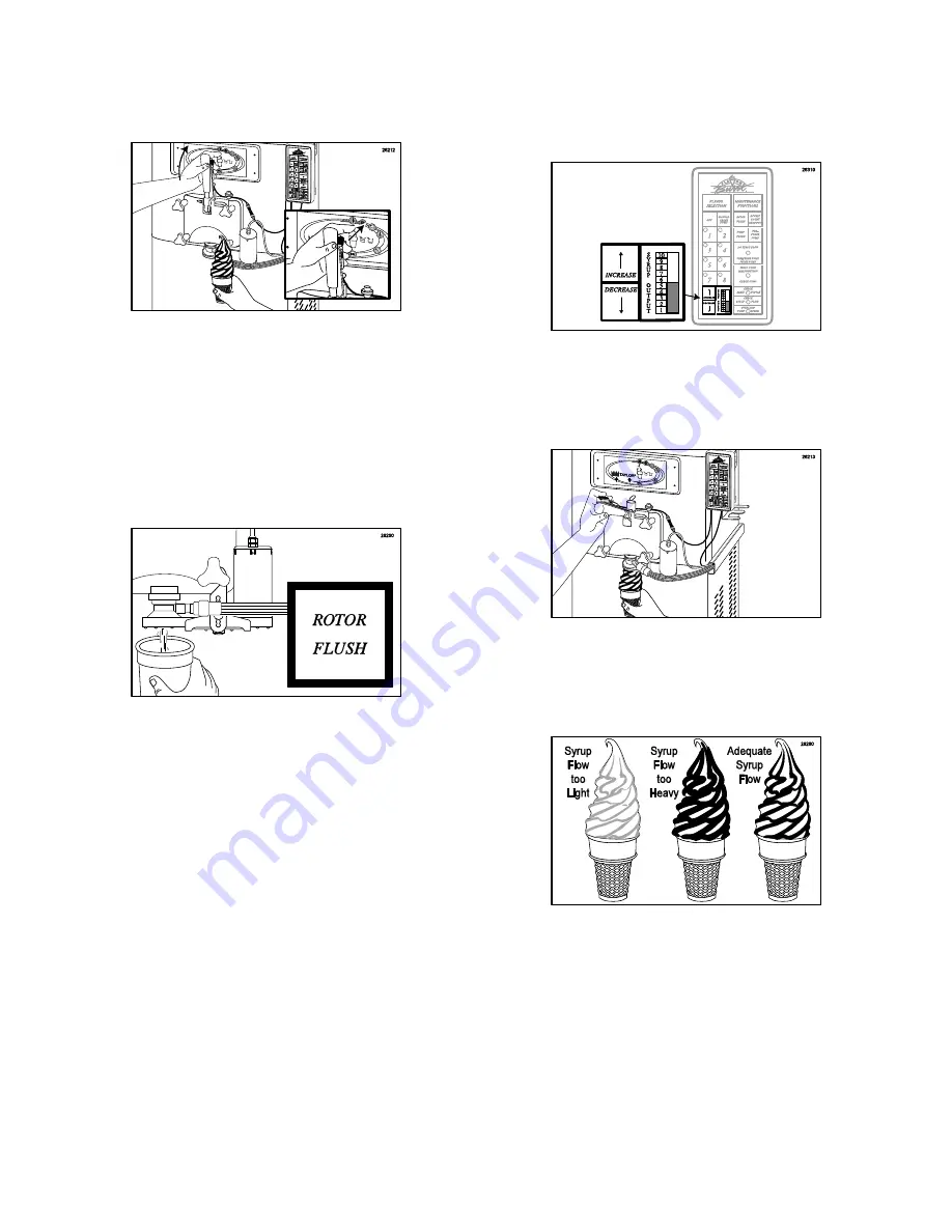
3. Release the Spigot Switch lever as you lift
the draw-handle when the desired amount
of product is drawn. (See Figure 174.)
Figure 174
NOTE:
WHEN THE SWITCH LEVER IS
RELEASED, THE SYRUP FLOW STOPS.
4. On occasion it may be desirable to sanitize
the Injector Head between servings. Simply
hold a container under the dispensing spout
and press ROTOR FLUSH. (See
Figure 175.)
Figure 175
Adjusting the Flavor Level
To produce the best Flavor Burst
®
serving, the
flavor output must be adjusted to the proper
level. Each Flavor Burst
®
flavor is formulated to
dispense at a standard level 5 and, generally
speaking, this is the recommended flavor level.
However, differences in freezers, product mix,
and consumer preferences will determine what
level is most appropriate for your operation.
Fortunately, the Flavor Burst
®
system is
adjustable for both flow and taste, and may be
quickly adjusted at any time between servings.
1. Follow the freezer manufacturer’s
instructions to adjust the desired product
flow with the adjustment knob.
2. Adjust the flavor output to #5 on the Keypad
Syrup Output bar by touching the
INCREASE or the DECREASE key. (See
Figure 176.)
Figure 176
3. Select one of the flavors on the Keypad by
touching the key (1-8), and draw a serving.
(See Figure 177.)
Figure 177
4. Determine if the serving needs more or less
syrup and adjust according to the following
instructions. (See Figure 178.)
Figure 178
5. TOO
HEAVY:
If the flavoring stripe tends to
run and appears to be unmixed with the soft
serve product, decrease the flavor by:
(Method A)
touching the DECREASE key,
or
(Method B)
increasing the flow of soft serve
by rotating the adjustment knob counter-
clockwise (loosen the screw).
Summary of Contents for FB 80-08
Page 5: ...4 General System Overview Figure 1 ...
Page 7: ...6 26 MIS 3067 OPEN CLOSED BUSHING 1 Strain relief for internal 9 Tube Assembly ...
Page 12: ...11 Syrup Pump and Related Parts Figure 4 ...
Page 14: ...13 Sanitizer Pump and Related Parts Figure 5 ...
Page 16: ...15 Electronic Parts and Connections Figure 6 ...
Page 18: ...17 Spare Parts Kit Figure 7 ...
Page 19: ...18 ...
Page 23: ...22 ...
Page 31: ...30 ...
Page 65: ...64 ...


