321023
81
11.2.6
Evaporator Fan Motor and Fan Blade
1. Remove the evaporator fan motor assembly (refer to Section 11.2.5).
2. Remove the evaporator fan blade by pulling the blade off the evaporator fan shaft.
3. Remove the fan motor by squeezing the motor retainer clips together to release the retainer.
4. Remove the retainer and slide the motor out.
5. Reverse the procedure to reassemble. The evaporator fan blade should be pushed down on the shaft
until it is seated.
11.2.7 Freezer
Thermistor
1. Remove the icemaker bucket.
2. Remove the icemaker by removing the hex head screws and unplugging the icemaker harness.
3. Remove the upper freezer shelves to access the freezer back.
4. Remove the freezer back hex head screws.
5. Rotate the back to expose the freezer thermistor.
6. Cut the wire at the thermistor and remove the thermistor.
11.2.8 Evaporator
Removal
NOTE:
Reclaim the refrigerant per instructions in “Service Procedures” before attempting evaporator
removal. To avoid system contamination, do not leave the system open for more than 10
minutes.
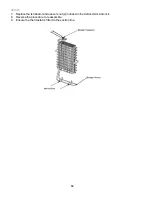
1. Remove all freezer shelving.
2. Remove the lower evaporator cover hex head screws.
3. Remove the evaporator cover.
4. Remove the defrost thermostat and defrost heater from the coil (refer to Sections 11.2.9 and
11.2.10).
5. Release the evaporator coil from the clips by pulling the coil off the clips.
6. Unsweat the evaporator coil after completing reclaiming procedures found in Section 12 of this
manual.
7. Reverse the procedure to reassemble.
11.2.9 Defrost
Terminator
(Thermostat)
1. Remove all freezer shelving.
2. Remove the lower evaporator cover hex head screws.
3. Remove the evaporator cover.
4. Disconnect the orange lead from the defrost heater.
5. Cut the brown lead close to the defrost terminator.
6. Unclip the defrost terminator from the evaporator coil.
Summary of Contents for RX256DT4X1
Page 11: ...321023 11 2 3 Refrigerant Flow...
Page 12: ...321023 12 2 4 Cabinet Air Flow...
Page 13: ...321023 13 2 5 Ice And Water Dispenser Diagram...
Page 14: ...321023 14 2 6 Water Valve Diagram...
Page 15: ...321023 15 2 7 Typical External Sweat Pattern...
Page 16: ...321023 16 3 INSTALLATION...
Page 17: ...321023 17...
Page 18: ...321023 18...
Page 76: ...321023 76 Ice Water Dispensing Board...
Page 78: ...321023 78 Mid Electronic Specification Control RX256DT4X1 RX256ET2B1 RX256ET2W1...
Page 104: ...321023 104 14 WIRING DIAGRAMS 14 1 Wiring Schematic RX256DT7X1...
Page 105: ...321023 105 14 2 Wiring Diagram RX256DT7X1...
Page 106: ...321023 106 14 3 Wiring Schematic RX256DT4X1 RX256ET2B1 RX256ET2W1...
Page 107: ...321023 107 14 4 Wiring Diagram RX256DT4X1 RX256ET2B1 RX256ET2W1...
Page 108: ...321023 108 NOTES...


