321023
29
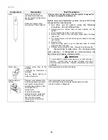
Component Description
Test
Procedures
Overload/Relay
When voltage is connected
and relay is cool, current
passes through relay to start
winding.
After a short time, current
heats the resistor in relay and
resistance will rise blocking
current flow through relay.
Start winding remains in the
circuit through run capacitor.
Solid state relay plugs directly
on compressor start and run
terminals. Relay terminals 2
and 3 are connected within
relay. Run capacitor is
connected to relay terminal 3.
L2 side of 120 VAC power is
connected to relay terminal 2.
1. Disconnect power to the refrigerator.
2. Remove relay cover and disconnect leads.
3.
Check resistance across terminals 2 and 3 with an ohmmeter:
Normal = 3 to 12 ohms
Shorted = 0 ohms
Open = infinite ohms
Ice maker
See “Ice Maker” section for
service information.
ECM condenser
motor
Condenser fan moves cooling
air across condenser coil and
compressor body.
Condenser fan motor is in
parallel circuit with
compressor.
Check resistance across coil.
Evaporator fan
motor
Evaporator fan moves air
across evaporator coil and
throughout refrigerator
cabinet.
1. Disconnect power to unit.
2. Disconnect fan motor leads.
3.
Check resistance from ground connection
solder. Trace to motor frame must not exceed .05
ohms.
4. Check for voltage at connector to motor with unit in
refrigeration mode and compressor operating.
Fresh food light
switch
Single pole, single throw
switch completes circuit for
light when door is open.
Check resistant across terminals.
Switch arm depressed
“NO” terminals
Open
Switch arm up
“NO” terminals
Closed
Freezer
light/interlock switch
Single pole, Double throw
switch completes circuit for
light when door is open.
Completes circuit for
dispenser when door is
closed.
Check resistant across terminals.
Switch arm depressed
“NO” terminals
Open
”NC” terminals
Closed
Switch arm not depressed
“NC” terminals
Open
“NO” terminals
Closed
Summary of Contents for RX256DT4X1
Page 11: ...321023 11 2 3 Refrigerant Flow...
Page 12: ...321023 12 2 4 Cabinet Air Flow...
Page 13: ...321023 13 2 5 Ice And Water Dispenser Diagram...
Page 14: ...321023 14 2 6 Water Valve Diagram...
Page 15: ...321023 15 2 7 Typical External Sweat Pattern...
Page 16: ...321023 16 3 INSTALLATION...
Page 17: ...321023 17...
Page 18: ...321023 18...
Page 76: ...321023 76 Ice Water Dispensing Board...
Page 78: ...321023 78 Mid Electronic Specification Control RX256DT4X1 RX256ET2B1 RX256ET2W1...
Page 104: ...321023 104 14 WIRING DIAGRAMS 14 1 Wiring Schematic RX256DT7X1...
Page 105: ...321023 105 14 2 Wiring Diagram RX256DT7X1...
Page 106: ...321023 106 14 3 Wiring Schematic RX256DT4X1 RX256ET2B1 RX256ET2W1...
Page 107: ...321023 107 14 4 Wiring Diagram RX256DT4X1 RX256ET2B1 RX256ET2W1...
Page 108: ...321023 108 NOTES...


