321023
100
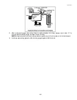
7. At 600 microns, close valve “A” to vacuum pump and allow micron reading in system to balance.
Micron level will rise.
•
If in 2 minutes, micron level stabilizes at 1000 microns or below, system is ready to be charged.
•
If micron level rises above 1000 microns and stabilizes, open valve “A” and continue evacuating.
•
If micron reading rises rapidly and does not stabilize, a leak still exists in system.
•
Close valve “A” to vacuum pump and valve “C” to vacuum gauge. Invert charging cylinder
and open charging cylinder valve “F” to add partial charge for leak checking. With leak
detector, check manifold connections and system for leaks. After locating leak, capture
refrigerant, repair leak, and begin at step 1.
13.10.2 Charging
NOTE:
Do not use captured or recycled refrigerant in units. Captured or recycled refrigerant voids any
warranty.
NOTE:
Charge system with exact amount of refrigerant. Refer to unit serial plate for correct refrigerant
charge. Inaccurately charged system will cause future problems.
To charge system:
1. Close valves “A” to vacuum pump and “C” to vacuum gauge and “E” to low side manifold gauge.
2. Set scale on dial-a-charge cylinder for corresponding HFC134a pressure reading.
3. Open valve “F” to charging cylinder and let exact amount of refrigerant flow from cylinder into
system.
Close valve.
Low side gauge pressure should rise shortly after opening charging cylinder valve as system pressure
equalizes through capillary tube.
If pressure does not equalize, a restriction typically exists at capillary/drier braze joint.
4. If pressure equalizes, open valve “E” to low side manifold gauge and pinch off high side drier
process tube.
5. Start compressor and draw remaining refrigerant from charging hoses and manifold into
compressor through compressor process tube.
6. To check high side pinch-off drier process tube, close valve “D” to high side gauge. If high side
pressure rises, repeat high side pinch-off and open valve “D”. Repeat until high side pinch-off
does not leak.
7. Pinch-off compressor process tube and remove charging hose. Braze stub closed while
compressor is operating.
8. Disconnect power. Remove charging hose and braze high side drier process tube closed.
9. Recheck for refrigerant leaks.
13.10.3 Refrigerant
Charge
Refrigerant charge in all capillary tube systems is critical and exact amount is required for proper
performance. Factory charges are shown on serial plate.
NOTE:
Do not use a refrigerant other than that shown on serial plate.
13.10.4
HFC134a Service Information
HFC134a has an ozone depletion potential (ODP) factor of 0.0 and a global warming potential (GWP)
factor of 0.27. HFC134a is not flammable and has acceptable toxicity levels.
Summary of Contents for RX256DT4X1
Page 11: ...321023 11 2 3 Refrigerant Flow...
Page 12: ...321023 12 2 4 Cabinet Air Flow...
Page 13: ...321023 13 2 5 Ice And Water Dispenser Diagram...
Page 14: ...321023 14 2 6 Water Valve Diagram...
Page 15: ...321023 15 2 7 Typical External Sweat Pattern...
Page 16: ...321023 16 3 INSTALLATION...
Page 17: ...321023 17...
Page 18: ...321023 18...
Page 76: ...321023 76 Ice Water Dispensing Board...
Page 78: ...321023 78 Mid Electronic Specification Control RX256DT4X1 RX256ET2B1 RX256ET2W1...
Page 104: ...321023 104 14 WIRING DIAGRAMS 14 1 Wiring Schematic RX256DT7X1...
Page 105: ...321023 105 14 2 Wiring Diagram RX256DT7X1...
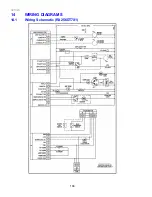
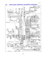
Page 106: ...321023 106 14 3 Wiring Schematic RX256DT4X1 RX256ET2B1 RX256ET2W1...
Page 107: ...321023 107 14 4 Wiring Diagram RX256DT4X1 RX256ET2B1 RX256ET2W1...
Page 108: ...321023 108 NOTES...


