321023
79
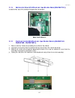
Mid Electronic Specification Control Panel (RX256DT4X1, RX256ET2B1, RX256ET2W1)
11.1.6
Electronically Controlled Damper
1. Remove the damper cover by removing the hex head screw and lifting off the damper.
2. Remove the foam insert by pulling it off the damper control.
3. Depress the two clips that hold the front of the damper in place to release the damper from the
assembly. Lift the damper out.
4. Disconnect the wires from the damper and remove the damper.
5. Reverse the procedure to reassemble.
11.1.7
Fresh Food Thermistor
1. Remove the damper cover by removing the hex head screw to expose the thermistor.
2. Unclip the thermistor from the assembly.
3. Cut the wires at the thermistor to remove.
11.1.8
Water Filter Assembly
1. Remove the filter cover by opening the cover and pulling the rear left side of the cover to the left to
release the cover from the holding pin.
2. The filter head can be released from the holding bracket by opening the tabs on the left side filter head
and pulling downward and to the left to release the filter head.
3. The tubing needs to be disconnected from the water valves in the machine compartment (refer to
Section 11.3.1).
4. After the tubing is disconnected from the water valves, pull the filter head and tubing out the front of
the unit.
5. Reverse the procedure to reassemble.
NOTE:
Make sure to note the tubing end colours when installing the new head and tubing assembly.
11.1.9
Water Tank Assembly
1. Remove the crisper drawers from the fresh food compartment.
2. Remove the hex screw holding the water tank to the rear bulkhead.
3. On the rear of cabinet, remove the hex screws holding the water valve cover plate.
4. Remove the plate and tubing away from the cabinet to expose the water valves and tubing.
5. Disconnect the water tube coming from the water tank from the secondary valve. Remove the
compression nut from the tubing.
6. On the front of the unit, remove the toe grill and disconnect the water coupler going to the water
dispenser.
7. Remove the compression nut from the water tubing on the cabinet side of the connection.
8. From the rear of cabinet, pull the water tube out of the conduit going to the dispenser.
9. From the inside of the fresh food compartment, pull the tubing up and out of the cabinet to complete
removal of the water tank.
10. Reverse the procedure to reassemble.
Summary of Contents for RX256DT4X1
Page 11: ...321023 11 2 3 Refrigerant Flow...
Page 12: ...321023 12 2 4 Cabinet Air Flow...
Page 13: ...321023 13 2 5 Ice And Water Dispenser Diagram...
Page 14: ...321023 14 2 6 Water Valve Diagram...
Page 15: ...321023 15 2 7 Typical External Sweat Pattern...
Page 16: ...321023 16 3 INSTALLATION...
Page 17: ...321023 17...
Page 18: ...321023 18...
Page 76: ...321023 76 Ice Water Dispensing Board...
Page 78: ...321023 78 Mid Electronic Specification Control RX256DT4X1 RX256ET2B1 RX256ET2W1...
Page 104: ...321023 104 14 WIRING DIAGRAMS 14 1 Wiring Schematic RX256DT7X1...
Page 105: ...321023 105 14 2 Wiring Diagram RX256DT7X1...
Page 106: ...321023 106 14 3 Wiring Schematic RX256DT4X1 RX256ET2B1 RX256ET2W1...
Page 107: ...321023 107 14 4 Wiring Diagram RX256DT4X1 RX256ET2B1 RX256ET2W1...
Page 108: ...321023 108 NOTES...

