321023
28
Component Description
Test
Procedures
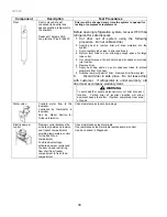
Capacitor
Run capacitor connects to relay terminal 3 and
L side of line.
Some compressors do not require a run
capacitor; refer to the Technical Data Sheet for
the unit being serviced.
WARNING
To avoid electrical shock which can cause
severe personal injury or death, discharge
capacitor through a resistor before
handling.
1. Disconnect power to refrigerator.
2. Remove capacitor cover and disconnect
capacitor wires.
3. Discharge capacitor by shorting across
terminals with a resistor for 1 minute.
4. Check resistance across capacitor terminals
with ohmmeter set on “X1 K” scale.
•
G o o d
—needle swings to 0 ohms and
slowly moves back to infinity.
•
O p e n
—needle does not move. Replace
capacitor.
•
S h o r t e d
—needle moves to zero and
stays. Replace capacitor.
•
H i g h r e s i s t a n c e l e a k
—needle jumps
toward 0 and then moves back to constant
high resistance (not infinity).
Condenser
Condenser is a tube and wire construction
located in machine compartment.
Condenser is on high-pressure discharge side
of compressor. Condenser function is to
transfer heat absorbed by refrigerant to
ambient.
Higher pressure gas is routed to condenser
where, as gas temperature is reduced, gas
condenses into a high pressure liquid state.
Heat transfer takes place because discharged
gas is at a higher temperature than air that is
passing over condenser. It is very important
that adequate airflow over condenser is
maintained.
Condenser is air cooled by condenser fan
motor. If efficiency of heat transfer from
condenser to surrounding air is impaired,
condensing temperature becomes higher.
High liquid temperature means liquid will not
remove as much heat during boiling in
evaporator as under normal conditions. This
would be indicated by higher than normal head
pressures, long run time, and high wattage.
Remove any lint or other accumulation that
would restrict normal air movement through
condenser.
From condenser, the refrigerant flows into a
post condenser loop that helps control exterior
condensation on flange, centre mullion, and
around freezer door. Refrigerant then flows
through the drier to evaporator and into
compressor through suction line.
Leaks in condenser can usually be detected by
using an electronic leak detector or leak
detection fluid. Look for signs of compressor oil
when checking for leaks. A certain amount of
compressor oil is circulated with refrigerant.
Leaks in post condenser loop are rare because
loop is a one-piece copper tube.
For minute leaks:
1. Separate condenser from rest of refrigeration
system and pressurize condenser up to a
maximum of 235 PSI with a refrigerant and
dry nitrogen combination.
2. Recheck for leaks.
WARNING
To avoid personal injury or death from sudden
eruption of high pressure gases, observe the
following:
Protect against a sudden eruption if high
pressures are required for leak checking.
Do not use high pressure compressed
gases in refrigeration systems without a
reliable pressure regulator and pressure
relief valve in the lines.
Summary of Contents for RX256DT4X1
Page 11: ...321023 11 2 3 Refrigerant Flow...
Page 12: ...321023 12 2 4 Cabinet Air Flow...
Page 13: ...321023 13 2 5 Ice And Water Dispenser Diagram...
Page 14: ...321023 14 2 6 Water Valve Diagram...
Page 15: ...321023 15 2 7 Typical External Sweat Pattern...
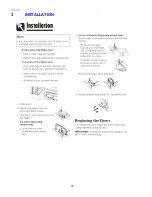
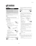
Page 16: ...321023 16 3 INSTALLATION...
Page 17: ...321023 17...
Page 18: ...321023 18...
Page 76: ...321023 76 Ice Water Dispensing Board...
Page 78: ...321023 78 Mid Electronic Specification Control RX256DT4X1 RX256ET2B1 RX256ET2W1...
Page 104: ...321023 104 14 WIRING DIAGRAMS 14 1 Wiring Schematic RX256DT7X1...
Page 105: ...321023 105 14 2 Wiring Diagram RX256DT7X1...
Page 106: ...321023 106 14 3 Wiring Schematic RX256DT4X1 RX256ET2B1 RX256ET2W1...
Page 107: ...321023 107 14 4 Wiring Diagram RX256DT4X1 RX256ET2B1 RX256ET2W1...
Page 108: ...321023 108 NOTES...


