background image


2.0 USER INTERFACE 


UL S2203 

CyberCat 254/1016 Operation Manual 

2-9 

FM 


P/N: 06-326-2 

Rev 6, 09/2015


2.2.1 

LOGGING ONTO THE SYSTEM 

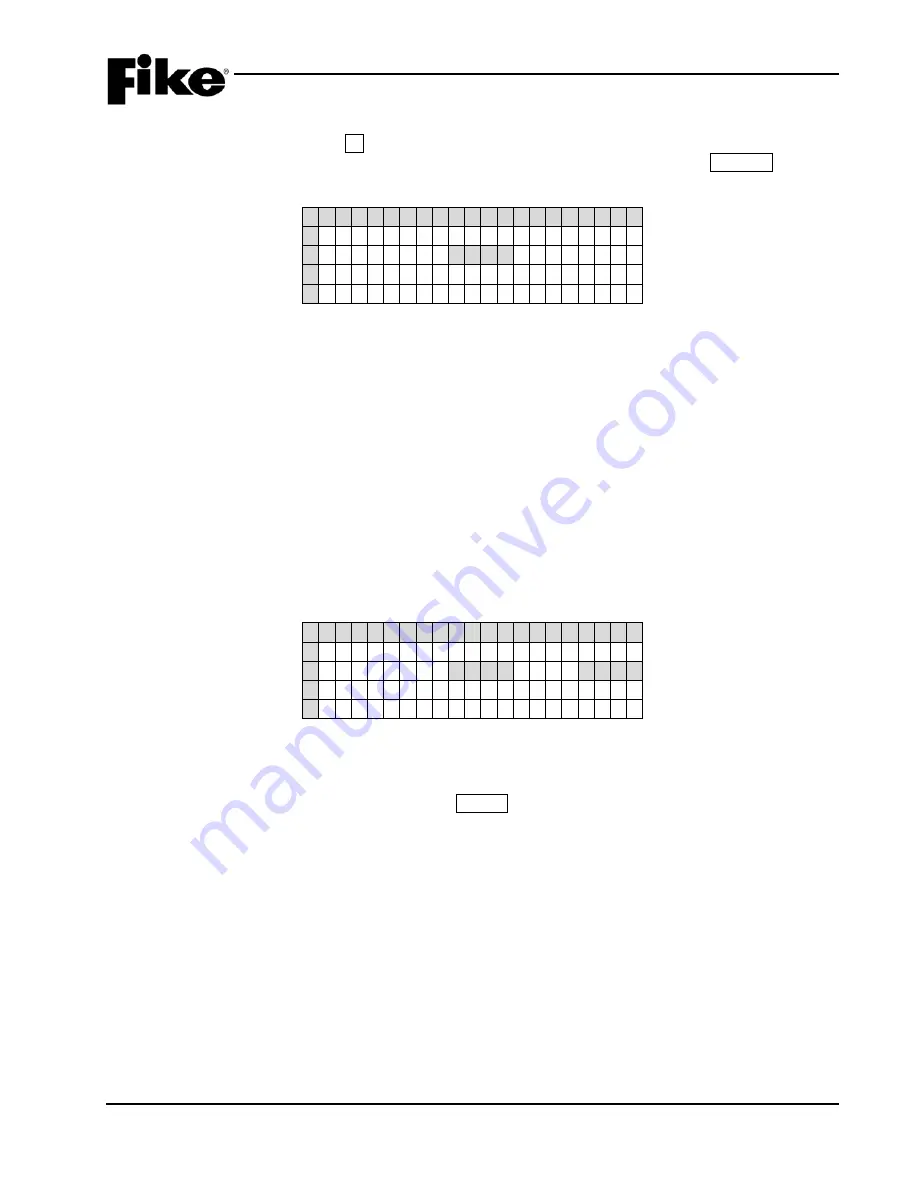
To log onto the system, press the F4  function  button  from the Top Level Menu.  The Password screen, as 
shown in Exhibit 2-10 will be displayed.  After entering a successful password, press the ESCAPE button to 
return to the Top Level menu. 


1  2  3  4  5  6  7  8  9  0  1  2  3  4  5  6  7  8  9  0 

      E  N  T  E  R    P  A  S  S W O R D       

                X  X  X  X                 

      A C C  E  S  S  :    D  E  N  I  E  D       

          C O D  E  :    X  X  X  X           

Exhibit 2-10:  Password Entry Screen 


Row B - Allows entry of a 4 digit password.  Use the 

◄► navigation buttons to move the cursor to the 

appropriate field and the +/- buttons (cycles through 0-9) to enter a password. 

Note:

 After entry of a Level 3 password, you have the ability to change the default administrator 

password as detailed in 2.2.2.  


Row C -  Displays the access level (Denied, Level 2  (A-H), Sys Admin, Factory) allowed with the 
password that has been entered.   


Row D -  Random 4 digit-code that changes periodically.  Used by the factory to gain access to the 
system if the Administrator password has been forgotten. 


2.2.2 

CHANGING THE SYSTEM ADMINISTRATOR PASSWORD 

After entering a successful Administrator level password you can change the default administrator password 
by changing the 4-digit number that appears on the far right of Row B, as shown in Exhibit 2-11.   


1  2  3  4  5  6  7  8  9  0  1  2  3  4  5  6  7  8  9  0 

      E  N  T  E  R    P  A  S  S W O R D       

                P  A  S  S  <  -  -  -  P  A  S  S 

      A C C  E  S  S  :    D  E  N  I  E  D       

          C O D  E  :    X  X  X  X           

Exhibit 2-11:  Password Entry Screen 


Row B (far right) - Allows entry of a new 4 digit password.  Use the 

◄► navigation buttons to move 

the cursor under each field and the +/- buttons to enter the new password (cycles through 0-9).  After 
completing the password change, press the ENTER button to confirm the change. 

Note:

  If the Administrator password is changed and then forgotten, you must contact  Fike and 

provide the 4-digit CODE displayed on Row D of the password entry screen  along with a 
completed password indemnification form.  


Summary of Contents for CyberCat 1016

Page 1: ...Operation Maintenance Manual P N 06 326 2 Rev 6 September 2015 10 064 CyberCat 1016 10 066 CyberCat 254 Addressable Fire Alarm Control System ...

Page 2: ...anty returns must be returned from an authorized Fike Distributor Contact Fike s Marketing department for further warranty information Fike maintains a repair department that is available to repair and return existing electronic components or exchange purchase previously repaired inventory component advance replacement All returns must be approved prior to return A Material Return Authorization MR...

Page 3: ...m Event Display 2 6 2 1 5 3 Top Level Menu 2 7 2 2 Password Protection 2 8 2 2 1 Logging onto the System 2 9 2 2 2 Changing the System Administrator Password 2 9 3 0 System Operation 3 1 3 1 General Operation 3 1 3 1 1 AC Trouble Delay 3 1 3 1 2 Daylight Savings 3 1 3 1 3 Silence Inhibit 3 1 3 1 4 Silence Reminder 3 2 3 1 5 State Counters 3 2 3 1 6 Network Operation 3 2 3 1 6 1 IP Network 3 2 3 1 ...

Page 4: ...5 Zone History 4 5 4 2 6 Erase History 4 5 4 2 7 Viewing Additional Event Information 4 6 5 0 System Diagnostics 5 1 5 1 Overview 5 1 5 2 Diagnosing Problems 5 1 5 3 Removing or Replacing Panel Components 5 1 5 4 Diagnostic Menu 1 5 2 5 5 1 Device Diagnostic 5 2 5 5 1 1 Device Type Location and LED Diagnostics 5 3 5 5 1 2 Device Serial Number Diagnostic 5 4 5 5 2 Value 1 Diagnostic 5 5 5 5 3 Value...

Page 5: ... 5 26 5 9 4 FAAST Detector Status 5 27 5 10 Voltages 5 28 6 0 System Maintenance 6 1 6 1 Overview 6 1 6 2 Routine Maintenance 6 1 6 3 Fuse Replacement 6 2 6 4 Panel Maintenance Menus 6 3 6 4 1 Maintenance Menu 1 6 3 6 4 1 1 Device Read 6 3 6 4 1 2 Device Address 6 4 6 4 1 3 Device Replace 6 5 6 4 1 4 Walk Test 6 7 A Panel Walk Test 6 8 B IR Tool Walk Test 6 9 6 4 1 5 Buzzer 6 9 6 4 2 Maintenance M...

Page 6: ...ory Display 3 11 3 9 Pre Alarm Display 3 12 3 10 Process Display 3 13 3 11 Zone Disable Display 3 14 3 12 Drill Display 3 15 3 13 Walk Test Display 3 16 3 14 Automatic Fan Restart Display 3 17 3 15 Manual Fan Restart Display 3 18 3 16 Detector Programming Features 3 19 4 1 Current Events Screen 4 1 4 2 Old Events Screen 4 1 4 3 Top Level Menu 4 2 4 4 History Menu 4 2 4 5 Alarm History Screen 4 3 4...

Page 7: ...Priorities Screen 5 22 5 31 Firmware Version Screen 5 23 5 32 Diagnostic Menu 5 5 24 5 33 Page Status Screen 5 24 5 34 Audio Priority Status Screen 5 25 5 35 Play Message ID Status Screen 5 26 5 36 FAAST Detector Selection Screen 5 27 5 37 FAAST Detector Status Screen 5 27 5 38 Control Board Test Points 5 28 6 1 Controller Fuse Locations 6 2 6 2 SPS Fuse Locations 6 2 6 3 Maintenance Menu 6 3 6 4 ...

Page 8: ...tion and Programming Manuals 1 Section 1 4 and 1 5 06 2011 Changed CyberCat manual P N from 06 326 1 to 06 326 and added peripheral bus programming feature to Exhibit 1 4 2 All Sections 12 2011 Added MNS features 3 Section 1 3 5 Appendix A 04 2012 Added FAAST detector and Voice Priorities 4 Sections 1 3 6 and Appendix A 08 2013 Added programming features for AHU restart audio sync and MNS activati...

Page 9: ...tact your installing distributor or you simply do not know who installed the system you can contact Fike Product Support at 800 979 FIKE 3453 Option 21 Monday through Friday 8 00 AM to 4 30 PM CST 1 3 SAFETY INFORMATION Important safety admonishments are used throughout this manual to warn of possible hazards to persons or equipment a WARNING Warnings are used to indicate the presence of a hazard ...

Page 10: ...ation with one another and the controller The controller is also responsible for providing the user interface performing system timing delivery of power to field devices storing system history events supervising SLC devices storing device custom messages communicating system events to peripheral devices and providing the system programming interface point 1 5 2 INTELLIGENT ADDRESSABLE DEVICES The ...

Page 11: ...rs The page can originate from the fire command center paging microphone or from any local operating console microphone AMPLIFIERS The Amplifier Assembly P N 10 2773 is designed to feed a single audio zone and provides an integral 24 Vdc visual notification appliance circuit The amplifier card is capable of providing up to 50 watts of audio output power to connected voice evacuation speakers The a...

Page 12: ... Disabled Walktest Y Enabled Disabled Display Latch of initial event N YES NO YES 8 Supervision Options Transformer Y 120VAC 240VAC Loop Style SLC Y 4 6 or 7 Class B A or X Ground Fault Level 1 N Enabled Disabled Enabled 2 Ground Fault Level 2 N Enabled Disabled Enabled 2 Main Battery Y Supervised Unsupervised Auxiliary Battery Y Supervised Unsupervised 3 Auxiliary Loop Module Present Y Enabled Di...

Page 13: ...sabled Drill Y Enabled Disabled Walktest Y Enabled Disabled Panel Sync Protocol Y Gentex System Sensor Gentex Visual Silence System Sensor Visual Silence Relays P2 Main Board Relays Relay Selection Y R1 R2 5 State Activation Y Alarm Pre Alarm 1 Pre Alarm 2 Supervisory Trouble Process Zone Disable Silenceable Y Non Silenceable Silenceable Zone Assignment Y 1 254 Circuit Y Enabled Disabled Drill Y E...

Page 14: ...Y 0 40 250 sec Silenceable Y Non Silenceable Silenceable Zone Assignment Y 1 254 Relay Y Enabled Disabled Drill Y Enabled Disabled P13 Relay Selection Y A B C D Module Y No Module Installed CRM4 CRPM Opt 1 CRPM Opt 2 Network Interface Card State Y Alarm Pre Alarm 1 Pre Alarm 2 Supervisory Trouble Process Zone Disable Restart Delay Y 0 40 250 sec Silenceable Y Non Silenceable Silenceable Zone Assig...

Page 15: ...hich is the original CyberCat format The ESP selection refers to an Expanded format Peripheral devices with 3 00 firmware or newer will used this command The EXP setting speeds up operation of the peripheral bus 3 If set to COMPACT a message filter within the panel is used to prevent transmission of certain history record events including the NEW DEVICE history messages This is done so that the pe...

Page 16: ...P Address Y 000 000 000 000 User Defined 6 Supervision IP Address Y 000 000 000 000 User Defined 7 Panel IP Supervision Y 000 000 000 000 4 History Transmits Y 1 10 Fike recommends 2 Supervision Timeout Y 1 59 Sec Min Hour 4 min default IP Time Y IP Time Disabled Accept IP Time Send IP Time 8 Notes 1 Defines the location of the panel with respect to others on the network 2 Defines if the respectiv...

Page 17: ... Supervisory Supervisory NL Drift Compensation Warning Trouble Y 50 100 Warning 80 Trouble 100 5 Walktest Y Walktest at Alarm Level Walktest with IR Walktest at 1 3 Device Summing Broadcast Thresholds for Summing OBS N Enabled Disabled 8 levels 0 5 ft 4 0 ft in 0 1 ft increments Summing Activation Level OBS N 1 0 10 ft 0 5 ft increments Summing Broadcast State No Disabled Alarm Summing Alarm Super...

Page 18: ... No State Alarm Summing Alarm Test Alarm Alarm Verification ON Pre Alarm 1 Pre Alarm 2 Supervisory Trouble Open Circuit Trouble Short Circuit Trouble Low Power Trouble Maintenance Trouble Process Zone Disable Switch Voice Alert Voice Evacuate Voice Page Voice Play Message ID Action Type Y No Action Activate on Any of 3 zones Activate on All of 3 zones Activate on Specific Device Activate on multip...

Page 19: ...ance N ON OFF Drift Compensation Warning Trouble Y 50 100 Warning 80 Trouble 100 5 Walktest Y Walktest at Alarm Level Walktest with IR Walktest at 1 3 Device Summing Broadcast Thresholds for Summing OBS N Enabled Disabled 8 levels 0 5 ft 4 0 ft in 0 1 ft increments Summing Activation Level OBS N 1 0 10 ft 0 5 ft increments Summing Broadcast State N Disabled Alarm Summing Alarm Supervisory Latching...

Page 20: ...L Drift Compensation Warning Trouble Y 50 100 Warning 80 Trouble 100 5 Walktest Y Walktest at Alarm Level Walktest with IR Walktest at 1 3 Device Summing Broadcast Thresholds for Summing OBS N Enabled Disabled 8 levels 0 5 ft 4 0 ft in 0 1 ft increments Summing Activation Level OBS N 1 0 10 ft 0 5 ft increments Summing Broadcast State N Disabled Alarm Summing Alarm Supervisory Latching Supervisory...

Page 21: ...ification Y Time 0 60 seconds Y Enabled Disabled Sensitivity Pre Alarm 1 2 Levels Y Enabled Disabled Y 70 F 190 F 5 F increments 3 Alarm Levels Day Night Y Fixed Temp 135 F 190 F 5 F increments 4 Y Rate of Rise 135 F 174 F 5 F increments 4 Walktest Y Walktest at 135 F Walktest with IR Remote Annunciator See Exhibit 1 8 for programming features Notes 1 CyberCat 254 has only one 1 addressable loop C...

Page 22: ...Enhance Off Smolder Enhance On Drift Compensation Y 50 100 Warning 80 Trouble 100 5 Walktest Y Walktest at Alarm Level Walktest with IR Walktest at 1 3 Device Summing Broadcast Thresholds for Summing OBS N Enabled Disabled 8 levels 0 5 ft 4 0 ft in 0 1 ft increments Summing Activation Level OBS N 1 0 10 ft 0 5 ft increments Summing Broadcast State N Disabled Alarm Summing Alarm Supervisory Latchin...

Page 23: ... Y No Short Detection Short Detection Voice MNS Priority Y 1 255 6 7 Msg 1 ID Y 0 16 8 Msg 2 ID Y 0 16 8 MNS Timeout Y 0 250 9 Notes 1 CyberCat 254 has only one 1 addressable loop CyberCat 1016 can have up to four 4 addressable loops 2 Can be assigned to 4 discrete zones 2 zone ranges or 1 range and 2 discrete zones 3 If monitor module function type is set to Detection an alarm verification time c...

Page 24: ... Module Loop Number of Device Y 1 4 1 Address of Device Y 1 254 Custom Message Y 60 character user defined 1 001 PULL STATION Loop 1 Address 001 Custom Message Y Default User Defined Zone Assignments Y 1 254 2 Input Function Y No Input Function Manual Alarm Notes 1 CyberCat 254 has only one 1 addressable loop CyberCat 1016 can have up to four 4 addressable loops 2 Can be assigned to 4 discrete zon...

Page 25: ...Activation State Y Alarm Summing Alarm Test Alarm Alarm Verification ON Pre Alarm 1 Pre Alarm 2 Supervisory Trouble Open Circuit Trouble Short Circuit Trouble Low Power Trouble Maintenance Trouble Process Zone Disable Switch Voice Alert Voice Evacuate Voice Page Voice Play Message ID MNS Message Active Action Type Y No Action Activate on Any of 3 zones Activate on All of 3 zones Activate on Specif...

Page 26: ... ON Pre Alarm 1 Pre Alarm 2 Supervisory Trouble Open Circuit Trouble Short Circuit Trouble Low Power Trouble Maintenance Trouble Process Zone Disable Switch Voice Alert Voice Evacuate Voice Page Voice Play Message ID MNS Message Active Action Type Y No Action Activate on Any of 3 zones Activate on All of 3 zones Activate on Specific Device Activate on multiple priority rows active Relay State Y ON...

Page 27: ...tion 2 Action 1 Alert Y No Timer Timer 1 Timer 2 Timer 3 5 Fire 1 or Fire 2 Alarm is Broadcast when Isolated Y Enabled Disabled Verification Timer Values Timer 1 Timer 2 Timer 3 Y 0 255 seconds Acclimate Acclimate Y Disabled Enabled Acclimate High Range Y Range 1 H 0 00046 ft 0 04980 ft Range 2 M 0 05 ft 0 09982 ft Range 3 M 0 1 ft 0 99645 ft Range 4 L 1 ft 3 98818 ft 6 Notes 1 CyberCat 254 has on...

Page 28: ... Y Fire 2 Fire 1 Action 2 Action 1 Alert Air Flow Trouble Boundary Y 0 100 off normal 20 default Air Flow Trouble Timer Y No Timer Timer 1 Timer 2 Timer 3 Security Test Button Functions Locked Y Enabled Disabled Isolate Button LCD Settings Locked Y Enabled Disabled Configuration Locked Y Enabled Disabled Can be Disabled Y Enabled Disabled Passcode Y 0 9999 1111 default Device Disable Isolate Butto...

Page 29: ...re Alarm 1 Pre Alarm 2 Supervisory Trouble Process PAS Inhibit Reset Silence Acknowledge Drill Fan Restart Y Latching Non Latching 3 Y Normally Open Normally Closed 4 Y Short Detection On Short Detection Off Input 2 Function Y No Input Function Pre Alarm 1 Pre Alarm 2 Supervisory Trouble Process AHU FD Key Y Latching Non Latching 3 Y Normally Open Normally Closed 4 Y Short Detection On Short Detec...

Page 30: ...lt 4 sec increments Alarm Verification Y Disabled Enabled Y Time 0 60 seconds Defaults Update Device Checksum Recalculate addressable device Configuration Checksums Y Yes No Defaults Reset Default Config Reset All Default Device Configurations Y Yes No Defaults Custom Messages Panel LCD Custom Message Line 2 Logo Y 20 character user defined Fike Corporation Addressable Devices Restores all device ...

Page 31: ...untdown Display Show Release Imminent Countdown Filter Y Show All Zone Countdowns Filter Countdown by Zone Do not show Countdown Programmable Key Functions 1 8 Y NO Function Reset Silence Acknowledge Drill Process Walktest IR Tool Step Alarm Step Supervisory Step Trouble Step All Fan Restart Zone Disable 1 Remote Display 2 and 10 Key Address Y 2 32 Custom Message Y 20 character user defined Fike R...

Page 32: ...evice Trouble Network Device Activation or Trouble Network Device Pre Alarm Network Device Activation or Pre Alarm Device selection Y PNL 1 128 Loop 1 4 Add 1 254 1 Activation State Y Alarm Pre alarm Process Trouble Supervisory Zone Disable Pre Discharge Release 2 Zone Assignments Y 1 254 2 Network Device selection Y PNL 1 128 Loop 1 4 Add 1 254 3 LED Illumination Pattern Active State Y Off Contin...

Page 33: ...r OK Activation State Y Alarm Pre Alarm Process Trouble Supervisory Zone Disable Pre Discharge Release 1 Zone Assignments Y 1 254 1 LED Illumination Pattern Active State Y Off Continuous Slow Blink Fast Blink Inactive State Y Off Continuous Slow Blink Fast Blink Silenced State Y Off Continuous Slow Blink Fast Blink Acknowledged State Y Off Continuous Slow Blink Fast Blink Multi Interface Module Ad...

Page 34: ...d On Zone PreAlarm On Zone Alarm On Zone Predischarge On Zone Release On Zone Test Alarm On Zone Action On Panel Silence On Panel Drill On Panel Walktest On Panel Comm OK On Panel Power OK On Panel Buzzer Active On Any Network Device Active On Any Network Device Trouble On Any Network Device PreAlm On All Network Device Active Off Any Network Device Active Off All Network Device Active On Any LED ...

Page 35: ...All Relay Modules All Releasing Modules All FAAST Sensors Y On Loop 1 4 Y Between 1 254 Y And 1 254 Y Select All Clear All Invert All Assignment by Zone Select Zones Y 1 254 Selection Options Y Select Clear Y All Zones Even Zones Odd Zones Y Between 1 254 Y And 1 254 Y Any Zone check box Y Select All Clear All Invert All Assignment by Network Device Select Network Devices Y 1 254 Example 002 1 001...

Page 36: ...e Trouble On Zone Supervisory On Zone Abort On Zone Disabled On Zone PreAlarm On Zone Alarm On Zone PreDischarge On Zone Release On Zone Test Alarm On Zone Action On Any Network Device On Any Network Device Trouble On Any Network Device PreAlm Off Any Network Device Off All Network Device 1 Assignment by Device Select Devices Y 1 254 Selection Options Y Select Clear Y All Addresses Even Addresses ...

Page 37: ...en 1 254 Y And 1 254 Y Any Zone check box Y Select All Clear All Invert All Assignment by Network Device Select Devices Y 1 254 Select Options Y All Addresses Even Addresses Odd Addresses All Photo Sensors All Photo Heat Sensors All Photo Duct Sensors All Ion Sensors All Heat Sensors All Monitor Modules All Dual Monitor Modules All Mini Monitor Modules All Pull Station Modules All Conventional Zon...

Page 38: ...trol Select Relay Actions when switch is pressed Y None On Auto Off 1 2 Action Start Y Action starts with confirmation address OR delay timer Action starts with confirmation address AND delay timer Confirmation Address Y Loop 0 4 Address 0 254 Relay Address Y Panel 0 128 Loop 0 4 Address 0 254 Delay relay activation Y 0 255 seconds Delay Timer Start Y Delay timer starts immediately Delay timer sta...

Page 39: ...e or PreAlm On Zone Process On Zone Trouble On Zone Supervisory On Zone Abort On Zone Disabled On Zone PreAlm On Zone Alarm On Zone PreDischarge On Zone Release On Zone Test Alarm On Zone Action On Panel Silence On Panel Drill On Panel Walktest On Panel Comm OK On Panel Power OK On Panel Buzzer Active On Any Network Device On Any Network Device Trouble On Any Network Device PreAlm On Any LED Activ...

Page 40: ... Control Select Relay Actions when switch is pressed Y None On Auto Off 1 2 Action Start Y Action starts with confirmation address OR delay timer Action starts with confirmation address AND delay timer Confirmation Address Y Loop 0 4 Address 0 254 Relay Address Y Panel 0 128 Loop 0 4 Address 0 254 Delay relay activation Y 0 255 seconds Delay Timer Start Y Delay timer starts immediately Delay timer...

Page 41: ...e PreAlm On Device Active or PreAlm On Zone Process On Zone Trouble On Zone Supervisory On Zone Abort On Zone Disabled On Zone PreAlm On Zone Alarm On Zone PreDischarge On Zone Release On Zone Test Alarm On Zone Action On Panel Silence On Panel Drill On Panel Walktest On Panel Comm OK On Panel Power OK On Panel Buzzer Active On Any Network Device On Any Network Device Trouble On Any Network Device...

Page 42: ...ill LED Test Graphic LED Configuration CFG1 thru CFG3 Y No Function Assigned Panel Silence Panel Drill Panel Walktest Panel Comm OK Panel Power OK Voice EVAC Switch Card Peripheral Address Y 2 32 Priority Level Y 0 254 Default 1 Copy EVAC Zones to Alert and Page Y Yes No Voice Evac Switch Groups 1 6 EVAC Switch Y Enabled Disabled EVAC Zone Assignments Y 1 254 ALERT Switch Y Enabled Disabled ALERT ...

Page 43: ...254 4 Silenceable Y Silence Non Silence Drill Y Enabled Disabled Walk Test Y Enabled Disabled Active During Fire Playback Y Enabled Disabled 5 Active During Fire Page Y Enabled Disabled 5 Active During MNS Playback Y Enabled Disabled 5 Active During MNS Page Y Enabled Disabled 5 NAC Delay Timeout Y 0 250 seconds Strobe OFF after Silence Y Enabled Disabled Contact Monitor Contact Y Disabled Enabled...

Page 44: ...signments Page Only State Y Drill Test Alarm Message 1 Y Message ID 1 16 1 Message 2 Y Message ID 1 16 1 Silence Y Silenceable Non Silence 2 Speaker Zones 1 4 Y 1 254 5 Amplifier Synchronization AMP Sync Y Enabled Disabled AMP Operation on Panel Network Y Play Cfg Msg ID Play Tones Play New Msg ID 7 New Msg ID Y None 1 16 7 Notes 1 Sets the first and second message that will be played in response ...

Page 45: ...g Y Normally Open Normally Closed Switch Configuration 01 10 Function Y No Function Assigned Voice Alert Voice Evacuate Voice Page Voice Record Page Voice Page To Alert Voice Page To EVAC Voice Play Message ID MNS Reset MNS Silence MNS Page MNS Record Page MNS Play Message ID Settings Y Zone Assignments Zones and Message ID 4 5 Priority Y 0 254 Default 1 2 3 Switch Timeout Y 0 250 min 0 6 Notes 1 ...

Page 46: ...onds Piezo Y Enabled Disabled Y Silenceable Non Silenceable Audio Bus Y Master Slave 1 Switch Configuration 01 13 Function Y No Function Assigned Voice Alert Voice Evacuate Voice Page Voice Record Page Voice Page To Alert Voice Page To EVAC Voice Play Message ID MNS Reset MNS Silence MNS Page MNS Record Page MNS Play Message ID Settings Y Zone Assignments Zones and Message ID Y Latching Non Latchi...

Page 47: ...vacuate Voice Page Voice Record Page Voice Page to Alert Voice Page to EVAC Voice Play Message ID MNS Silence MNS Page MNS Record Page MNS Play Message ID AHU Restart Zone Y 0 254 2 3 Settings Y Relay Action Settings Zone Assignments Zone and Message ID 4 Y Latching Non Latching Latching 5 Priority Y 0 254 Default 1 1 Switch Timeout Y 0 250 min 0 5 Message ID1 Y 1 16 6 Message ID2 Y 1 16 6 Notes 1...

Page 48: ...starts with confirmation address AND delay timer Confirmation Address Y Panel 0 128 Loop 0 4 Address 0 254 Relay Address Y Panel 0 128 Loop 0 4 Address 0 254 Delay Timer Y 0 255 seconds Delay timer Start Y Delay timer starts immediately Delay timer starts after confirmation address activates Zone Assignments Selection table active for Voice Functions only Select Zones Y 1 254 Selection Options Y S...

Page 49: ...K On Panel Power OK On Panel Buzzer Active On Any Network Device Active On Any Network Device Trouble On Any Network Device PreAlm On All Network Device Active Off Any Network Device Active Off All Network Device Active On Any LED Active On All LED Active Off Any LED Active Off All LED Active On Alarm Silence On Supervisory Silence On Trouble Silence On Alarm Silence Inhibit On Device Active or Pr...

Page 50: ...elay Modules All Releasing Modules All FAAST Sensors Y On Loop 1 4 Y Between 1 254 Y And 1 254 Y Select All Clear All Invert All Assignment by Zone Select Zones Y 1 254 Selection Options Y Select Clear Y All Zones Even Zones Odd Zones Y Between 1 254 Y And 1 254 Y Any Zone check box Y Select All Clear All Invert All Assignment by Network Device Select Devices Y 1 254 Select Options Y All Addresses...

Page 51: ...ailable Point ID Information Loop ID Y 1 4 1 Point ID Information Address ID Y 1 254 1 VESDA Scanner VESDA Zone Number Y 1 254 State Y Alarm Supervisory Trouble Device Enabled Y Enabled Disabled Custom Message Y 20 Characters user defined CUSTOM MESSAGE VZ001 Custom Message Y Default Custom Message User Defined Custom Message Zone Assignments Y 1 253 4 zones available Sector 1 Zone Number Y 1 254 ...

Page 52: ...1 0 INTRODUCTION 1 44 CyberCat 254 1016 Operation Manual UL S2203 Rev 6 09 2015 P N 06 326 2 FM Reserved for future use ...

Page 53: ... K E C O R P O R A T I O N 0 8 0 0 0 0 A 1 0 1 1 2 0 1 0 A L 0 0 0 S U 0 0 0 T R 0 0 0 SYSTEM STATUS LEDs SYSTEM STATUS LEDs LCD DISPLAY WINDOW CONTROL BUTTONS NAVIGATION BUTTONS MENU FUNCTION BUTTONS HISTORY NAVIGATION BUTTONS Exhibit 2 1 CyberCat Main Display Access to almost all of the control and navigation buttons are blocked with the system enclosure door in the closed and locked position Th...

Page 54: ...ady after you Silence the event either locally at the main display or remotely at a remote display unit Silencing the system turns off the panel s integral audible and all notification appliance circuits that are programmed as Silenceable Turns off when the panel is reset or another system event occurs NFPA 72 requires that a silenced panel resound every 24 hours Pre Alarm 1 Red Flashes when the p...

Page 55: ...o execute the designated system function by pressing the button A brief functional description of each button is provided below DRILL Press this button to manually activate all outputs and notification appliance circuits assigned for Drill Function in the configuration Press RESET to clear the Drill activation ACKNOWLEDGE Press this button to Acknowledge an Alarm Trouble or Supervisory State Deact...

Page 56: ...display They can also be used when cycling through the event history The Step Alarm button only cycles forward in events These buttons allow you to go forward and backward through the events ESCAPE Press this button to toggle from Off Normal Event display if events are present to System Normal no events preset to Top Level Menu If in a menu this button EXITS the current menu and returns to the pre...

Page 57: ... R 0 0 0 Exhibit 2 4 System Normal Display Row A Provides a standard system message including panel name and firmware version Row B Displays a 20 character custom message that can be customized Row C Displays the current time and date set for the system Row D Displays the number of Alarm AL Supervisory SU and Trouble TR events currently present on the system Note When a panel has cleared all local...

Page 58: ... event is displayed toggles the display to show more detail related to the event displayed Press the F1 function button to toggle Rows A and B to display the Panel Loop Address of event as shown in Exhibit 2 6 Press F1 again to return to the System Event display 1 2 3 4 5 6 7 8 9 0 1 2 3 4 5 6 7 8 9 0 A P N L 0 0 1 L O O P 1 A D D R 0 0 1 B C U S T O M M S G P A N E L 0 0 1 C H H M M S S A M M D D...

Page 59: ... to display the panel s Configuration menu The configuration menus allow you to change the operating parameters of the CyberCat system The configuration menus are password protected and require entry of a User Level or higher password to view or an Administrator Level password to change the configuration parameters F2 HISTRY Press the F2 function button to display the panel s History menu From thi...

Page 60: ...passwords and a single System Administrator password to be assigned by the system installer The available security access levels are described as follows Password Level Designation Privileges Default door panel closed View system events on LCD display Access to STEP buttons for reviewing system history 1 Customer door panel open no password entered All default privileges plus Access to system cont...

Page 61: ...d with the password that has been entered Row D Random 4 digit code that changes periodically Used by the factory to gain access to the system if the Administrator password has been forgotten 2 2 2 CHANGING THE SYSTEM ADMINISTRATOR PASSWORD After entering a successful Administrator level password you can change the default administrator password by changing the 4 digit number that appears on the f...

Page 62: ...2 0 USER INTERFACE 2 10 CyberCat 254 1016 Operation Manual UL S2203 Rev 6 09 2015 P N 06 326 2 FM Reserved for future use ...

Page 63: ...dules transmit all information from the panel output to the Supervising Station Since Loss of AC is non critical and secondary power is available Supervising Stations typically need not see immediate AC power low troubles AC power loss trouble will not immediately be sent to the dialer for AC power low or loss Trouble if it is the only fault The communication will wait the programmed amount of tim...

Page 64: ... zone numbers on the network e g Zone 1 spanning multiple panels operates as one zone for all inputs and outputs or leave the panel zones independent from each other e g Zone 1 on panel 1 is independent from zone 1 on panel 2 If the panel is NOT configured to respond to the zone event that is transmitted it will respond by logging the event in the panel s history buffer and displaying it on the pa...

Page 65: ... take precedence over all other panel operations The smoke control functions can be activated automatically or manually Automatic activation of the smoke control system shall be initiated in response to signals received from a single smoke detector heat detector waterflow switch or a combination of these devices Automatic activation shall have the highest priority over all other sources of automat...

Page 66: ...and audible incoming call signal at the FCC The individual originating the call hears a tone until the incoming call is manually connected to the telephone riser by the system operator Up to five 5 remote telephones may be connected to the telephone riser simultaneously The system operator at the FCC can also connect the telephone riser to the paging system allowing paging via the telephone system...

Page 67: ...l perform a power up reset long reset when power AC or DC is first applied to the CyberCat controller or when a RESET command is initiated either from the main controller display peripheral device or a remote input module configured for reset Prior to performing the system reset the panel will display the following screen for 4 seconds 1 2 3 4 5 6 7 8 9 0 1 2 3 4 5 6 7 8 9 0 A R E C O R D N E W D ...

Page 68: ...lowing 1 Green AC POWER LED illuminates 2 Supervises loop devices requests device status every 8 seconds If device fails to report panel will indicate DEVICE MISSING trouble within 1 minute Likewise if a new device is present on the system and not in the panel configuration a DEVICE NOT IN CONFIG trouble will be reported 3 LED on SLC devices will blink every 5 seconds 4 SLC devices communicate the...

Page 69: ...ber XXXX and the total number of current events YYYY How to respond to an Alarm Waterflow Event 1 Press the ACKNOWLEDGE button to silence the panel sounder only The panel ALARM LED will change from flashing to steady The control panel will send an acknowledge message to remote displays history buffer printers PC monitoring stations and DACT 2 Press the F1 button to toggle Rows A and B on display t...

Page 70: ...Y Y Y Y D E V E N T X X X X O F Y Y Y Y Exhibit 3 5 Alarm Verification Display Row A Displays activation of Alarm Verification time delay Row B Displays the 20 character custom message for the device Row C Displays the Time and Date of Event Row D Displays the event number XXXX and the total number of current events YYYY How to respond to an Alarm Verification Event 1 Press the F1 button to toggle...

Page 71: ...arm event Row B Displays the 20 character custom message for the device Row C Displays the Time and Date of Event Row D Displays the event number XXXX and the total number of current events YYYY How to respond to a Summing Alarm Event 1 Press the ACKNOWLEDGE button to silence the panel sounder only The panel ALARM LED will change from flashing to steady The control panel will send an acknowledge m...

Page 72: ...ssage for the device Row C Displays the Time and Date of Event Row D Displays the event number XXXX and the total number of current events YYYY How to respond to a Trouble Event 1 Press the ACKNOWLEDGE button to silence the panel sounder only The panel TROUBLE LED will change from flashing to steady The control panel will send an acknowledge message to remote displays history buffer printers PC mo...

Page 73: ...Row C Displays the Time and Date of Event Row D Displays the event number XXXX and the total number of current events YYYY How to respond to a Supervisory Event 1 Press the ACKNOWLEDGE button to silence the panel sounder only The panel SUPERVISORY LED will change from flashing to steady The control panel will send an acknowledge message to remote displays history buffer printers PC monitoring stat...

Page 74: ...re Alarm Display Row A Displays the device type associated with the Pre Alarm event Row B Displays the 20 character custom message for the device Row C Displays the Time and Date of Event Row D Displays the event number XXXX and the total number of current events YYYY How to respond to a Pre Alarm Event 1 Press the ACKNOWLEDGE button to silence the panel sounder only The panel PRE ALARM LED will c...

Page 75: ...restored and no buttons are pressed 1 2 3 4 5 6 7 8 9 0 1 2 3 4 5 6 7 8 9 0 A P R O C E S S I N P U T B C U S T O M M E S S A G E L A D R C H H M M S S A M M D D Y Y Y Y D E V E N T X X X X O F Y Y Y Y Exhibit 3 10 Process Display Row A Displays the device type associated with the Process event Row B Displays the 20 character custom message for the device Row C Displays the Time and Date of Event ...

Page 76: ...Row B Displays the 20 character custom message for the Zone Row C Displays the Time and Date of Event Row D Displays the event number XXXX and the total number of current events YYYY How to respond to a Zone Disable Event 1 Press the ACKNOWLEDGE button to silence the panel sounder only The panel DISABLED LED will change from flashing to steady The control panel will send an acknowledge message to ...

Page 77: ...t 3 12 Drill Display Row A Displays the Drill active event Row B Displays the 20 character custom message for the active device Row C Displays the Time and Date of Event Row D Displays the event number XXXX and the total number of current events YYYY The following devices and panel circuits can be configured to participate in system drills Addressable Supervised Control Module drill enabled by def...

Page 78: ...lows then switches to the System Status Display if all events are restored and no buttons are pressed 1 2 3 4 5 6 7 8 9 0 1 2 3 4 5 6 7 8 9 0 A W A L K T E S T A L A R M B C U S T O M M E S S A G E L A D R C H H M M S S A M M D D Y Y Y Y D E V E N T X X X X O F Y Y Y Y Exhibit 3 13 Walk Test Display Row A Displays the Walk Test active event Row B Displays the 20 character custom message for the ac...

Page 79: ...a normally energized relay and will activate for any ALARM event in any of its zones CRM4 fan restart can be configured for manual or automatic operation using the control panel s FAN RESTART MODE function that can be found in Configuration Menu 4 F5 Relays F4 Fan Restart Mode Automatic Restart Upon activation of an ALARM event the CRM4 relays will activate and remain active even after the control...

Page 80: ...d will activate for any ALARM event in any of its zones Like the CRM4 relays each addressable relay can be configured with a restart delay 0 255 seconds Upon activation of an ALARM event each AHU Shutdown relay will activate and remain active even after the control panel is reset After reset the fan restart sequence must be initiated manually using any of the following sources 1 control panel s AH...

Page 81: ...ion will be broadcast Alarm Verification state will then be OFF The control panel LED s and piezo do not operate during the Alarm Verification state An Alarm Verification event is recorded in the event history buffer 3 4 2 PRE ALARM Pre Alarms are used for performing an early warning of a fire alarm There are two levels of Pre Alarms that may be configured Pre Alarm 1 and Pre Alarm 2 for each dete...

Page 82: ...ve two separate alarm thresholds one less sensitive alarm threshold during operational hours one more sensitive alarm threshold during non operational hours Each input detector has two alarm sensitivity thresholds Night Alarm Level is always used on all detectors Day Alarm Level is only used if Day Night Holiday Schedule are selected If Day Night Holiday is selected as active the On and Off times ...

Page 83: ...ummee to calculate the SUM for the SUMMING ALARM To set up this operation a single detector is selected as a SUMMER The Summer can look at information from 8 photo or ion same type as summer and same loop as summer can include the summer detectors called the SUMMEE s The Summer will total the obscuration percentages received from each summee defined The Summer can be set to alarm from 1 10 ft prog...

Page 84: ...3 0 SYSTEM OPERATION 3 22 CyberCat 254 1016 Operation Manual UL S2203 Rev 6 09 2015 P N 06 326 2 FM Reserved for future use ...

Page 85: ... listing of system event messages and suggested corrective actions 4 2 VIEWING HISTORY As current system events occur the display will toggle to show the current system event Current events are those that have taken place since the last Reset of the panel With the panel door closed you must use the STEP buttons to cycle through current events on the display STEP ALARM Press to step through the cur...

Page 86: ... E V E N T S C F 2 S U P E R V F 5 Z O N E D F 3 T R O U B L F 6 E R A S E Exhibit 4 4 History Menu The CyberCat has 5 history screens that are accessible without having to enter a password Each screen allows you to view the history buffer by event type Alarm Supervisory Trouble All Events and by Zone This is the same function as pressing the STEP buttons on the CyberCat display Press the correspo...

Page 87: ...ber of current Alarm events present on the system Use the buttons on the display to scroll through all Alarm events in the history buffer 4 2 2 SUPERVISORY HISTORY The SUPERVISORY History screen allows you to view the current supervisory events 800 total present on the system since the last Reset of the panel From the History Menu press the F2 button to display the Supervisory History screen 1 2 3...

Page 88: ... all Trouble events in the history buffer 4 2 4 EVENTS HISTORY The EVENTS History screen allows you to view all of the current system events present on the system since the last Reset of the panel From the History Menu press the F4 button to display the Events History screen 1 2 3 4 5 6 7 8 9 0 1 2 3 4 5 6 7 8 9 0 A P O W E R U P R E S E T B C U S T O M M S G P A N E L 0 0 1 C 0 1 0 0 0 0 P 0 1 0 ...

Page 89: ... D Displays the Zone event number in the order received and the total number of Zone events present on the system Use the buttons on the display to scroll through all Zone events in the history buffer 4 2 6 ERASE HISTORY The ERASE History screen allows you to erase the CyberCat s 3 200 event history buffer This feature requires prior entry of a successful Level 3 Administrator password From the Hi...

Page 90: ...he event on Row A of the display 1 2 3 4 5 6 7 8 9 0 1 2 3 4 5 6 7 8 9 0 A P N L 0 0 1 L O O P 1 A D D R 0 0 1 B C U S T O M M E S S A G E 1 0 0 1 C 0 1 0 0 0 0 P 0 1 0 1 2 0 0 7 D E V E N T 0 0 1 O F 0 0 0 4 Exhibit 4 13 Additional Information Screen Press the F2 button to display all three lines of the custom message associated with the event displayed 1 2 3 4 5 6 7 8 9 0 1 2 3 4 5 6 7 8 9 0 A G...

Page 91: ...L COMPONENTS OR FIELD DEVICES If it is determined that a panel component is defective and needs to be replaced 1 Use the system programming software to download the current system configuration from the panel 2 Disconnect the system batteries then remove AC power ICaution Removing or replacing system components when power is applied will damage the equipment 3 Disconnect field wiring from componen...

Page 92: ...stic screen F1 Addressable Device Diagnostic F2 Panel Diagnostics Ground Fault F3 Panel Diagnostics F4 LED Test F5 Main Board Processor Communications F6 Diagnostics Menu 2 5 4 1 DEVICE DIAGNOSTIC The Device Diagnostic menu allows you to diagnose problems with the addressable devices connected to the panel s signaling line circuits SLCs From the Diagnostic Menu 1 press the F1 button to display the...

Page 93: ...D Displays the device typepresent found connected on the addressable loop at the specific address Same device types as shown in Row C description below Press the F1 button to view the device missing counter for the device at the cursor position Press the F1 button again to return to previous screen L Allows you to light the LED for the device red green flash To light the device LED use the buttons...

Page 94: ...V I C E L O O P Exhibit 5 4 Device S N Diagnostic Screen Row A LOOP allows you to select the loop number represented by N Use the buttons to position the cursor under the field then press the buttons to change to desired loop 1 4 Row A ADDRESS Allows you to select the address of the device to display Use the buttons to position the cursor under the field then press the buttons to increment decreme...

Page 95: ...egulator on main for AC power 120VAC 200 255 240VAC 206 255 Row A L1 Loop 1 short circuit detect Normal 10 255 For all RS485 circuits the value is 0 ohms Row B 24V Main panel 24VDC power 140 255 Row B A2 Voltage Regulator on main for AC power 120VAC 200 255 240VAC 206 255 Row B L2 Loop 2 short circuit detect Normal 10 255 CyberCat 1016 ONLY Row C B1 Battery circuit on Main controller Normal 31 255...

Page 96: ...Screen Row A C1 Loop 1 supervision trouble 100 Row A C1 Loop 1 supervision trouble 100 Row A L3 Loop 3 short circuit detect Normal 10 255 Row B C2 Loop 2 supervision trouble 100 Row B C2 Loop 2 supervision trouble 100 Row B L4 Loop 4 short circuit detect Normal 10 255 CyberCat 1016 ONLY Row C C3 Loop 3 supervision trouble 100 Row C C3 Loop 3 supervision trouble 100 Row D C4 Loop 4 supervision trou...

Page 97: ...ostic Menu 1 press the F5 button to view the Cyclic Redundancy Count screen 1 2 3 4 5 6 7 8 9 0 1 2 3 4 5 6 7 8 9 0 A P R O G R A M C R C A A 3 6 B M A I N P I C V E R 5 0 0 B C A U X L P I C V E R D P R E S S E N T E R T O C A L C Exhibit 5 8 CRC Diagnostic Screen Row A Displays the main system processor CRC value Row B Displays the main loop SLC 1 2 processor firmware version Row C Displays the ...

Page 98: ...on set points from the selected VESDA unit From Diagnostic Menu 2 screen press the F2 button to view the VESDA 1 Diagnostic screen 1 2 3 4 5 6 7 8 9 0 1 2 3 4 5 6 7 8 9 0 A V E S D A Z O N E N U M 0 0 1 B C U R R E N T 0 0 0 0 0 F T C A L A C D F 1 F 2 Exhibit 5 11 VESDA 1 Diagnostics Screen Row A Allows you to select the VESDA zone number to view Use the arrow buttons to position the cursor in on...

Page 99: ... 0 B T Y P E B O S C H D A C T C C O M M A N D S S E N T 0 0 0 0 0 D C O M M A N D S R C V D 0 0 0 0 0 Exhibit 5 13 Peripheral Diagnostics Screen Row A ADR Allows you to select the peripheral address to view Use the buttons to select the Peripheral ID to diagnose Row A SUP Displays the number of times the panel sent a supervision message without a response Row A MAX Counts the number of times a su...

Page 100: ...bove 200 A value below 90 indicates an open condition Row B A Displays the analog to digital conversion values from the supervision of the series 500 loop negative terminal If the wire is attached correctly the value shown should be below 20 A value above 090 indicates an open condition Row B SH Displays the short circuit detection value for the series 500 loop A normal value is above 160 A value ...

Page 101: ... 2 screen press the F5 button to view the VESDAnet Communications screen 1 2 3 4 5 6 7 8 9 0 1 2 3 4 5 6 7 8 9 0 A V E S D A Z O N E N U M 0 0 1 B P O L L T X 0 0 0 0 R X 0 0 0 0 C N E T W T X 0 0 0 0 R X 0 0 0 0 D C O M M I N T E R V A L 1 0 0 0 M S Exhibit 5 17 VESDAnet Communication Screen Row A Allows you to select the VESDA zone device number to display Row B Poll TX Displays the number of po...

Page 102: ...controller and networked panels being monitored by this panel From the Diagnostic Menu 3 screen press the F1 button to view the Network Diagnostic 1 screen 1 2 3 4 5 6 7 8 9 0 1 2 3 4 5 6 7 8 9 0 A P A N E L I D 0 0 1 N O N E B N E T I D S 0 0 1 0 2 0 T X 0 C 1 2 3 4 5 6 7 8 9 0 1 2 3 4 5 6 7 8 9 0 D Exhibit 5 19 Network Diagnostics 1 Screen Row A Displays the network Panel ID 1 128 and the locati...

Page 103: ...or Last If the network module reports a different position or isolated then the counter on the left side of 000 009 increments The number on the right is the configurable threshold for trouble initiation The factory default is 9 Row C Displays the number of trouble events recorded for Class A network wiring troubles This only applies to network modules configured as First When the module reports a...

Page 104: ...at must be sent to the Network PIC before the next panel missing command can be verified The factory default is 10 Use the arrow buttons to position the cursor over the field then press the buttons to change the value at cursor Row D Allows you to change the ratio of network history transmission reception commands to history reception only commands to the network module The value of the field on t...

Page 105: ...es for testing purposes starting with the event number shown on Row C When ON the panel will transmit an event every 10 seconds Use the buttons to change the value at cursor The default value is OFF The event number shown on Row C will increment after each transmission Row C Allow you to select a specific event number e g CURRENT EVENT 033 If automatic transmission is OFF pressing ENTER will trans...

Page 106: ... of checksum errors noted by system processor from the Main PIC ERR of checksum errors noted by system processor from the Aux PIC Row D TXD of commands received by system processor from Main and Aux pics since last reset will rollover ERR of TXD checksum errors Note Press the ENTER button while this menu is displayed to clear the counters and restart at 0 This provides a starting point to monitor ...

Page 107: ...essed for a zone assigned to this amp STATUS PAGE A PAGE switch on a voice evacuation card has been pressed for a zone assigned to this amp STATUS PAGE W RR A PAGE WITH RECORD AND REPEAT switch on a voice evacuation card has been pressed for a zone assigned to this amp STATUS FIRE MESSAGE A PLAY FIRE MESSAGE switch is active STATUS MNS MESSAGE A PLAY MNS MESSAGE switch is active STATUS MNS PAGE An...

Page 108: ...D2 Fire message 1 16 MNS message 101 116 MNS Page 251 MNS R R 252 Fire Page 253 Fire R R 254 C Active speaker circuit and audio source See table below for description of values D Audio bus troubleshooting Increments periodically if the amplifier does not receive any valid packets on the audio bus Once the counter reaches max value of 255 it stays at 255 until the fault clears Once the amp starts r...

Page 109: ...xternal 240 1 2 3 4 External External External External 9 1 4 Internal Internal 52 1 2 3 External External Internal 131 1 2 4 Internal Internal External 10 2 4 Internal Internal 56 1 2 4 External External Internal 132 3 4 Internal External 11 1 2 4 Internal Internal Internal 60 1 2 3 4 External External Internal Internal 133 1 3 4 Internal Internal External 12 3 4 Internal Internal 64 3 External 1...

Page 110: ...hrough J NOT USED K Audio bus master or slave Slave 0 Master 1 L Contact monitor Not active 0 Active 1 M Paging control card switch priority level 0 highest 8 lowest N Contact monitor priority level 0 highest 8 lowest O Microphone trouble No trouble 0 Not connected 1 check pin 3 on P8 Wiring trouble 1 2 check pin 2 8 on P8 Wiring trouble 2 4 check pin 1 7 on P8 Wiring trouble 3 6 check pin 1 2 7 8...

Page 111: ...ndition The drill switch has been pressed P Zone is in Page condition A page switch for this zone has been pressed R Zone is in Page with Record and Repeat condition A page with record and repeat switch for this zone has been pressed F Zone is in Play Fire Message condition A play fire message switch for this zone has been pressed M Zone is in Play Mass Notify Message condition A play MNS message ...

Page 112: ...VACUATE FIRE PAGE includes Page with Record and Repeat FIRE MESSAGE per zone ALL PAGE Page to Alert Page to EVAC Page All and Page All with Record and Repeat MNS PAGE per zone MNS MESSAGE per zone 5 7 3 2 VOICE ZONES PRIORITIES The Voice Zones Priorities screen allows you to view the current priority and status of the selected zone number From the Voice Zones screen press the F2 button to view the...

Page 113: ...ity level 5 7 4 PERIPHERAL FIRMWARE VERSION The Peripheral Firmware Version screen allows you to view the firmware version of the selected peripheral bus device From the Diagnostic Menu 4 screen press the F4 button to view the Firmware Version screen 1 2 3 4 5 6 7 8 9 0 1 2 3 4 5 6 7 8 9 0 A P E R I P H E R A L A D D R 0 2 B T Y P E D I G I T A L P A G I N G C F I R M W A R E V E R S I O N D X X X...

Page 114: ...us F4 FAAST Detector Status F5 Not Used F6 Menu 1 5 8 1 PAGE STATUS The Page Status screen allows you to view the general paging status of the panel There are no selectable items on this screen From the Diagnostic Menu 5 screen press the F1 button to view the Page Status screen 1 2 3 4 5 6 7 8 9 0 1 2 3 4 5 6 7 8 9 0 A A L E R T T O P A G E O F F B E V A C T O P A G E O F F C D Exhibit 5 33 Page S...

Page 115: ...switch has control priority over another switch that is programmed for the same operation A switch with a lower priority setting cannot override a switch with a higher priority Switch with the same priority setting can override another switch with the same priority setting or a lower priority setting Row A nnn Displays the current priority level active 0 254 at the panel 000 indicates that no prio...

Page 116: ...s Screen Row B Zone Allows you to select the zone number 1 253 that will be displayed in Row B Use the buttons to increment or decrement the zone number The primary and secondary message numbers for the selected zone will be shown as P nnn S xxx where nnn and xxx indicates the primary and secondary message numbers being played Fire message 1 16 MNS message 101 116 Row C Silence Indicates the silen...

Page 117: ...d 1 2 3 4 5 6 7 8 9 0 1 2 3 4 5 6 7 8 9 0 A L A D D S F L V T I M B C F G A S P F D L E D 0 C D I S D I R F U A I R F L O D C O M D B L F M 0 0 0 Exhibit 5 37 FAAST Detector Status Screen Row A L ADD Displays the loop 1 4 and address number 1 253 of the FAAST device being displayed An asterisk will be displayed in each status field when the applicable fault is active SF Sensor Fault Sensor fault h...

Page 118: ...o TP1 Check this point if AC power is applied but the system does not seem to operate properly Exhibit 5 38 Control Board Test Points LOOP VOLTAGE Nominally 24 VDC with a data communication pulse that drops down to a level between 0 5 VDC During normal operation a meter should measure anywhere from 0 24 VDC It should never measure a constant 0 VDC GROUND FAULT TP1 to Chassis With a normal panel an...

Page 119: ...be corrected If a defect or malfunction is not corrected at the conclusion of system inspection testing or maintenance the system owner or owner s designated representative shall be informed of the impairment in writing 6 2 ROUTINE MAINTENANCE Certain components of the CyberCat require replacement at regular intervals even though no obvious sign of failure is present Batteries Lead Acid Replace ev...

Page 120: ...iliary Power circuit 2 4 Amp P N 02 11412 F5 Auxiliary Power circuit 3 4 Amp P N 02 11412 F F F3 Exhibit 6 1 Controller Fuse Locations If the Supplemental Power Supply is installed it is equipped with five replaceable fuses standard automotive as shown in Exhibit 6 2 These fuses provide over current protection for the controller and are rated as follows F1 Primary AC Power input 15 Amp P N 02 4174...

Page 121: ... corresponding function button to display the selected maintenance screen F1 Read device loop address F2 Assign loop address to device F3 Replace device sequence F4 Select Walktest mode F5 Disable on board buzzer F6 Maintenance Menu 2 6 4 1 1 DEVICE READ The Device Read screen allows you to see the address and device type of the most recent device attached to the loop From the Maintenance Menu pre...

Page 122: ...nder the Loop and Address fields then use the buttons to increment decrement the fields Row D Press the ENTER button to start the automatic address function See Exhibit 6 6 Note Once ENTER is pressed the panel needs to see a NEW DEVICE record for the device Either add the new device to the loop at this time or remove and replace the single device This menu does not alter the configuration or the p...

Page 123: ...e process 6 4 1 3 DEVICE REPLACE The Device Replace screen allows you to replace a sensor type device already connected to the panel with a new like device and write the configuration of the original device into the new device A successful Level 2 or higher password is required to access this feature From the Maintenance Menu press the F3 button to access the Device Replace screen 1 2 3 4 5 6 7 8 ...

Page 124: ... S S E N T E R D W H E N C O M P L E T E Exhibit 6 11 Device Replace Screen The panel will send the device configuration stored in the panel to the new device The serial number stored in the panel for the replaced device will be replaced with the serial number from the new device The following screen will be displayed to show that the process is proceeding 1 2 3 4 5 6 7 8 9 0 1 2 3 4 5 6 7 8 9 0 A...

Page 125: ...utton is pressed to toggle between the two walk test modes Mode 1 Buzzer ON the local piezo will also sound with the activation of the alarm events Mode 2 Buzzer OFF the local piezo will be silent with the activation of the alarm events Once the proper walk test mode has been selected the panel is locked into the walk test mode and all normal panel operations are suspended The panel will remain in...

Page 126: ...F1 CONFIG F6 MENU 2 F6 MENU 3 F2 WALK to ENABLE walk test operation for the panel This requires an administrator level password to change Note Detectors programmed for walk test with IR will automatically issue a TEST ALARM message upon activation of the walk test mode through the control panel Detectors will indicate that they are in the walk test mode by blinking their LEDs green then red contin...

Page 127: ...vice or select next device to be tested if IR single select is enabled Device being tested exits the test mode and the device LED returns to normal operation flash green every 5 seconds 8 After all devices are tested download the panel history for testing records 9 Disable IR communication for respective addressable loop Devices require significantly more power when their IR receivers are continua...

Page 128: ... voice system amplifiers are activated for mass notification MNS they cannot be reset using the standard control panel reset switches The MNS Reset function provides a means for the system operator to reset the MNS system from the control panel local or network Resetting the MNS system does not impact the operation of any active Fire Alarm inputs or outputs From the Maintenance Menu 2 screen press...

Page 129: ... required for this switch to function 6 4 2 3 SWITCH OPERATION When configured for City of Chicago operation the CyberCat panel s DRILL and SILENCE switches on the main display are disabled in order to comply with local code requirements The Switch Timeout screen allows the user to temporarily enable the DRILL and SILENCE switches for a period of 0 24 hours for inspection and testing purposes This...

Page 130: ...ading Press ENTER to start the Reading process Row D NNNN shows the total number of devices the panel will read This number will decrement each time a device has been read For systems with a large number of devices to be read the screen will return to the System Normal display after a few minutes of inactivity The System Normal display will indicate the current status of the configuration read unt...

Page 131: ...tor that aligns with the address number on Row B Only FAAST detectors are displayed Non FAAST detectors are shown as F indicates that the detector is not isolated or disabled I indicates that the detector is isolated D indicates that the detector is disabled Row D Displays the actions that are available for the FAAST detector selected in Row C F1 RD forces a read of the diagnostic condition of the...

Page 132: ...6 0 SYSTEM MAINTENANCE 6 14 CyberCat 254 1016 Operation Manual UL S2203 Rev 6 09 2015 P N 06 326 2 FM Reserved for future use ...

Page 133: ...1 MNS R F2 PRIORITY F6 MENU 2 CONFIGURATION MENU 2 2 4 F1 TIME F2 SILENC F3 POWER F4 DAY SEN F1 DAYTIME SEN RANGE F2 SELECT HOLIDAYS F5 ZONE F1 SIGNAL CODE F2 ZONE XXX ALARM SETS F6 MENU 3 CONFIGURATION MENU 3 2 4 F2 HISTRY HISTORY MENU F1 PERIPH F1 DEVICE F1 ALARM 1 4 F2 SOURCE F2 SUPERV 1 4 F3 SPEED F3 TROUBL 1 4 F2 WALK F4 CMD SET F4 EVENTS 1 4 F3 GROUND 4 F5 ZONE 1 4 F5 SEN CHG F6 ERASE 3 4 F6...

Page 134: ... F3 NETW 3 4 F1 RESET NETW MOD F5 NETWORK F1 ID S F1 CUSTOM MESSAGE F4 HISTORY 1 4 F2 MODULE F5 BRD COM 1 4 F3 ZONES F5 SELECT ALL F6 MENU 4 DIAGNOSTIC MENU 4 F6 DESELECT ALL F1 AMP STA 1 4 F4 HIST TR F2 PER DAT 1 4 F5 SWITCH F1 CUSTOM MESSAGE F6 MENU 6 CONFIGURATION MENU 6 2 4 F3 VOICE Z 1 4 F1 VOICE STATUS F1 IP ADR F1 CLR IP ADDR HIST F4 PER FV 1 4 F2 ZONE PRIORITY F2 IP SUP F1 CUSTOM MESSAGE F...

Page 135: ......

Page 136: ...704 SW 10 th Street P O Box 610 Blue Springs Missouri 64013 Tel 816 229 3405 Fax 816 229 0314 www fike com ...

Reviews: