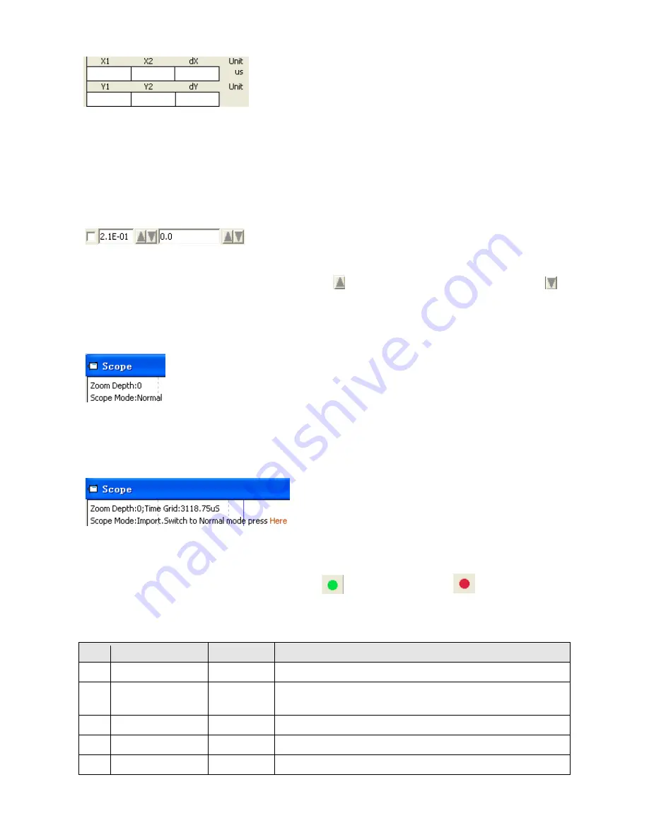
40
Figure 5-14: Cusor data
Export: Exports the sampled data as a .scope file.
Import: Imports a .scope file and shows the oscillogram in the scope window.
Reread: Rereads the last scope data out of the controller and shows the oscillogram in the scope window.
Auto: If the checkbox Auto is checked, the oscillogram is auto-scaled.
If Auto is not checked, the oscillogram is scaled by scale and offset value in following field:
Figure 5-15: Scale and offsetr data
Scale and offset value can be increased by pressing the
button, and can be reduced by pressing the
button. If Small scale checkbox is checked, scale value changing step is changed to 10% as before.
Scope Mode: On the upper left side of the oscillogram the Scope Mode “Normal” or “Import” is shown.
-Normal: all buttons are active.
Figure 5-16: Scope mode: Normal
-Import: If the oscillogram is an import from a .scope file, the scope mode will be “Import”, in this mode the
Start, Reread button will be inactive. The “Import” mode can be quit by clicking the “Here” on the hint.
Figure 5-17: Scope mode: Import
5.7 Error display and error history
Error: Click Controller->Error Display or click the
button (which turns red
if an error occurs).
The Error Display window appears. It shows the last errors.
Table 5-7: Error_State(2601.00) Information
Bit
Error name
Error code
Description
0
Extended Error
Refer to object “Error_State 2”(2602.00)
1
Encoder not
connected
0x7331
No communication encoder connected
2
Encoder internal
0x7320
Internal encoder error
3
Encoder CRC
0x7330
Communication with encoder disturbed
4
Controller
0x4210
Heatsink temperature too high


