20
Note
Be aware of the different (default) setting of the digital I/O configuration after setting the
command type in EA02 or changing a motor type. When settings are changed, an active
function may be assigned to digital inputs which have not been in use before as a result of
the new defaults, and signals applied to the digital inputs may inadvertently trigger DIN
functions. It’s recommended to proceed with EASY menu settings with unplugged X4
connector or disconnected power supply to the digital inputs.
It’s strongly recommended to process the EASY menu with switched off drive power input.
Double check X4 wiring before switching on drive power input.
Information
The EASY and tunE menus are designed to be set with button originally. For safety reasons,
the EASY and tunE menus provide only the parameters EA00, EA01 and tn00 if any of
following cases happen, case 1: the user initializes the parameters by any way; case 2: a
motor type is connected to the controller which is different to the in EA01 confirmed one;
case 3: the motor type setting has been changed by other way rather than through EA01
(e.g. by PC software).
After the motor type becomes confirmed in EA01, the contents of the entries in the menus
get default values and the menus get back the full function.
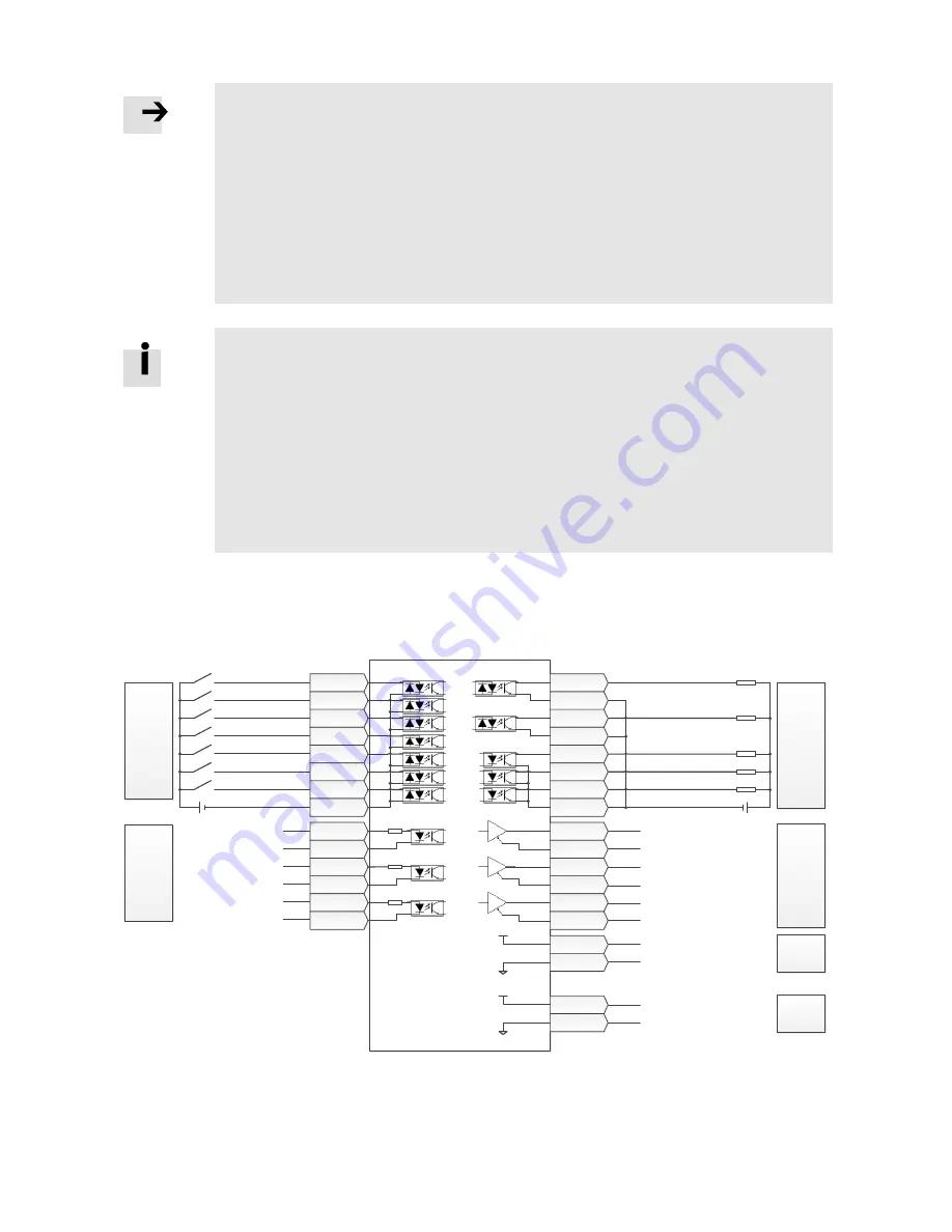
The following pages show four different I/O function configurations based on different command type
settings in EA02 and typical related wiring diagrams for I/O connector X4.
Pulse train mode configuration, command types 0, 1 or 2 in EA02:
Digital
Input
Enable
Reset Errors
Start Homing
P limit+
P limit-
Home Signal
Input Common
PUL+ / CW+ / A+
PUL- / CW- / A-
DIR+ / CCW+ / B+
DIR- / CCW- / B-
Z+
Z-
Impulse
Command
(<500k)
OUT1+
OUT1-
OUT2+
OUT2-
OUT3
OUT4
OUT5
COMO
1
3
5
7
9
11
20
13
ENCO_A
ENCO_/A
ENCO_B
ENCO_/B
ENCO_Z
ENCO_/Z
34
36
30
32
26
28
+5V
GND
22
24
+5V
GND
VDD
VEE
15
17
+24V
VEE
DIN1
DIN2
DIN3
DIN4
DIN5
DIN6
DIN7
COMI
4
6
8
10
12
14
16
2
MA+
MA-
MB+
MB-
MZ+
MZ-
27
29
31
33
35
18
Self-adapt
Self-adapt
Self-adapt
Internal 24V
Output
Internal 24V
Internal 24V Output-
Internal 5V
Output
Internal 5V
Internal 5V Output-
Encoder
Output
Encoder Out A+
Encoder Out A-
Encoder Out B+
Encoder Out B-
Encoder Out Z+
Encoder Out Z-
Digital
Output
Ready
Motor Brake
Pos Reached
Zero Speed
Error
Output Common
Figure 4-4: X4 wiring in pulse train mode


