36
OPERATION
NOTE:
The flame start control unit detects faults in
the flame starting system; these faults are in-
dicated through various flash codes dis-
played on the preheating indicator (see
FAULTS AND REMEDIAL ACTIONS
Section 4.1).
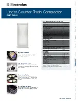
6.3 Jump starting
Use jump leads to connect positive terminal to
positive terminal and negative terminal to
negative terminal of the assisting battery.
Operation_Pic_number:1
When battery partially discharged, jump star-
ting from another tractor.
●
Connect jump leads to the discharging trac-
tor's battery in sequence (1-4).
●
Start the engine of the second tractor.
●
Start engine after ca. 15 minutes.
●
Once the engine is running, disconnect the
cables in reverse order.
WARNING:
A 24 Volt current destroys electronic
components.
Do not allow contact between the
non-insulated parts of the battery
clamps. The jump lead connected to
the positive terminal should not
come into contact with any
electrically conductive parts of the
vehicle - danger of shorting!
To avoid sparks, always attach the
jump lead clamps in the correct
order.
Fig.46
Jump starting a partially discharged battery
with another battery.
●
Connect jump leads to the assisting battery in
sequence (1-4).
●
Start engine immediately.
●
Once the engine is running, disconnect the
cables in reverse order.
If the attempt is unsuccessful.
●
Connect jump leads to two assisting batteries
in sequence (1-8).
●
Start engine immediately.
●
Once the engine is running, disconnect the
cables in reverse order.
Text-module
NOTE:
Assisting batteries must have a voltage of
12 volts and around the same capacity (Ah)
as the discharged batteries.
When jump starting, the engine must be
started immediately after connecting, other-
wise the assisting battery will become disch-
arged as well.
Do not reverse the terminal polarity.
Use only jump leads with sufficient cross-
section, and with insulated clamps.
Do not disconnect a discharged battery from
the on-board electrical system.
If the tractor is left unused for an extended
period, the battery can be recharged with a
battery charger (12V).
Summary of Contents for 916 Vario
Page 8: ...8 NUMERICAL INDEX ...
Page 172: ...172 CARE AND MAINTENANCE ETWiring diagram 22 3 Power supply UB 930 900 000 004 Sheet 2 ...
Page 173: ...173 CARE AND MAINTENANCE ETWiring diagram 22 4 Grounding layout 930 900 000 004 Sheet 3 ...
Page 174: ...174 CARE AND MAINTENANCE ETWiring diagram 22 5 Starter control 930 900 000 004 Sheet 4 ...
Page 175: ...175 CARE AND MAINTENANCE ETWiring diagram 22 6 Cold start system 930 900 000 004 Sheet 5 ...
Page 177: ...177 CARE AND MAINTENANCE ETWiring diagram 22 8 STVZO lighting Sheet 1 930 900 000 004 Sheet 7 ...
Page 179: ...179 CARE AND MAINTENANCE ETWiring diagram 22 10 Turn signal system 930 900 000 004 Sheet 9 ...
Page 183: ...183 CARE AND MAINTENANCE ETWiring diagram 22 14 Rear work lamps 930 900 000 004 Sheet 13 ...
Page 186: ...186 CARE AND MAINTENANCE ETWiring diagram 22 17 Heater 930 900 000 004 Sheet 16 ...
Page 191: ...191 CARE AND MAINTENANCE ETWiring diagram 22 22 Comfort bus K bus 930 900 000 004 Sheet 21 ...
Page 192: ...192 CARE AND MAINTENANCE ETWiring diagram 22 23 Instrument panel 930 900 000 004 Sheet 22 ...
Page 197: ...197 CARE AND MAINTENANCE ETWiring diagram 22 28 Transmission control 930 900 000 004 Sheet 27 ...
Page 199: ...199 CARE AND MAINTENANCE ETWiring diagram 22 30 Suspension 930 900 000 004 Sheet 29 ...
Page 200: ...200 CARE AND MAINTENANCE ETWiring diagram 22 31 PTO 930 900 000 004 Sheet 30 ...
Page 202: ...202 CARE AND MAINTENANCE ETWiring diagram 22 33 LBS 930 900 000 004 Sheet 32 ...
Page 203: ...203 CARE AND MAINTENANCE ETWiring diagram 22 34 Engine control 930 900 000 004 Sheet 33 ...
Page 262: ...262 TECHNICAL DATA ...
Page 266: ...266 ALPHABETICAL INDEX ...