


5 Shipping and Lifting Machine
Operations Manual
CR 820 T
Date May 2020
Page 5-4
1
2
3
4
5
6
8
9
11
12
14
7
16
17
18
19
20
21
22
23
24
10
13
15
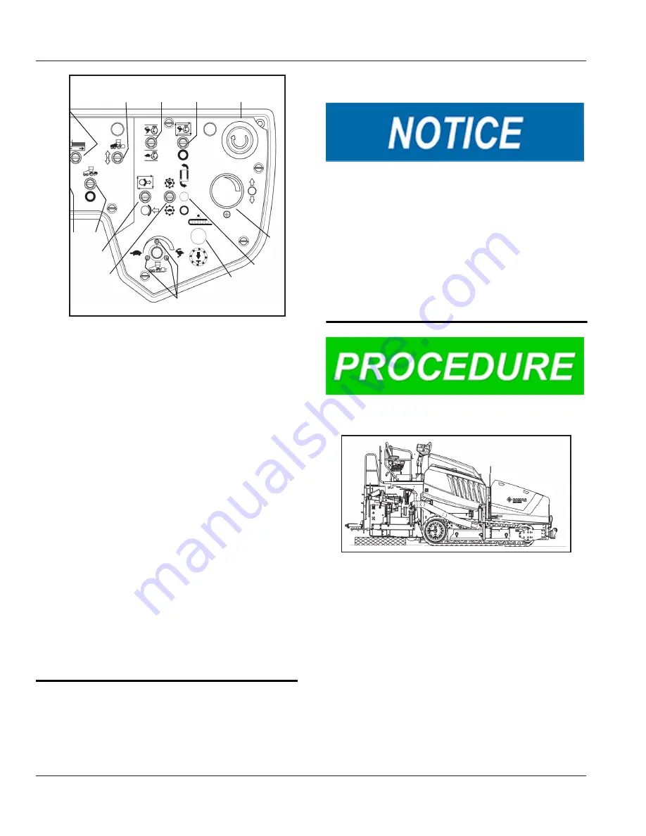
Figure 5.3
- Control Panel
5.
Bring the engine to full throttle using the
Throttle Override switch (8) (toggle the
switch up).
6.
Enable to Auto-Brake release system by
toggling the Auto Brake Switch up. The
Brake icon on the display will go from
solid Red to alternating between Red and
Green. The Brake Icon will change to solid
Green when the FNR (12) is moved out
of the neutral position indicating that the
brake release valve is energized.
7.
Move the FNR (12) to F so the machine
can be driven onto the trailer.
8.
Slowly increase the setting on the Paver
Speed Control Knob (14) until the paver
starts moving. It is safer to use a slow
speed while loading or unloading.
9.
Watch the area at the rear of the tractor to
be sure that components do not drag on
the ground.
10.
Back the machine off the trailer.
Preparation for Transport
Do not set the screed on nails, rivets, or bolts.
These can cause damage to the screed bottom.
Chaining directly to the screed, truck hook, or tow
arms could damage the equipment. When chain-
ing the machine to the trailer, all chains should be
secured to the machine frame only.
NOTE:
Both front and rear pair of cables/chains
must be of equal length so that the machine s rais-
es evenly from side-to-side.
1.
Load the machine onto the trailer or truck.
Figure 5.4
- Screed On Blocks
2.
Lower the screed onto blocks at each end
and in the center of the screed.
Summary of Contents for Bomag CR 820 T Tier 4
Page 2: ...Intentionally Left Blank ...
Page 3: ...Table of Contents Date May 2020 Page 1 Operations Manual CR 820 T TABLE OF CONTENTS ...
Page 10: ...Table of Contents Operations Manual CR 820 T Date May 2020 Page 8 Intentionally Left Blank ...
Page 11: ...1 INTRODUCTION Date May 2020 Page 1 1 Operations Manual CR 820 T 1 INTRODUCTION ...
Page 16: ...1 INTRODUCTION Operations Manual CR 820 T Date May 2020 Page 1 6 Intentionally Left Blank ...
Page 17: ...2 Safety Date May 2020 Page 2 1 Operations Manual CR 820 T 2 SAFETY ...
Page 38: ...2 Safety Operations Manual CR 820 T Date May 2020 Page 2 22 Intentionally Left Blank ...
Page 39: ...3 Technical Data Date May 2020 Page 3 1 Operations Manual CR 820 T 3 TECHNICAL DATA ...
Page 41: ...4 Operator Controls Date May 2020 Page 4 1 Operations Manual CR 820 T 4 OPERATOR CONTROLS ...
Page 99: ...9 Maintenance Date May 2020 Page 9 1 Operations Manual CR 820 T 9 MAINTENANCE ...
Page 126: ...9 Maintenance Operations Manual CR 820 T Date May 2020 Page 9 28 Intentionally Left Blank ...
Page 127: ...10 Storage Date May 2020 Page 10 1 Operations Manual CR 820 T 10 STORAGE ...
Page 129: ...Intentionally Left Blank ...


