97
Revision date: 12.02.16
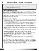
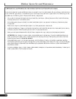
Black-out System Installation
ATTACH LEADING EDGES TO DRIVE PIPES
1. Leading edges are secured to the drive pipes with 115177 drive pipe
clamps. Slip one 115177 clamp onto each of the four drive pipes per bay.
NOTE:
LVDWLJKW¿WRQWKHGULYHSLSH&ODPSVFDQHLWKHUEHEHQW
open slightly to slip over the drive pipes, or drive pipes can be unspliced in
the necessary locations to guide the 115177 clamps into place. Re-splice
after 115177 has been slipped on.
2. Push the leading edges tight against the sealing edge of the rafter headers.
3. Using M6x75MM t-bolts (113317) and M6 nuts (113310), secure the leading edges to the 115177 for all leading
HGJHVLQDOOED\V+HDGVRIWKH7EROWV¿WXSLQWROHDGLQJHGJHFKDQQHODQGZLOOJULSZKHQWZLVWHGLQWRSODFH
when nut is tightened. Tighten so drive pipe will not slip through the clamp during operation.
IMPORTANT:
Verify that the rubber gasket of the leading edges remains tightly pressed against the rafter
KHDGHUVDVWKHOHDGLQJHGJHVDUHDWWDFKHGWRWKHGULYHSLSH7KLVHQVXUHVDQHI¿FLHQWOLJKWVHDOZKHQWKHV\VWHP
is operational. See diagrams below.
A
A
B
B
C
C
Leading Edge
Drive Pipe
115177
Drive Pipe
Clamp
*some framing
removed for clarity
115177
Drive Pipe Clamp
113317 T-bolt
&
113310 nut
M6x75MM t-bolt (113317)
&
M6 nut (113310
*keder sealing strip and rubber
gasket removed for clarity
*keder sealing strip and rubber
gasket removed for clarity
*keder sealing strip and rubber
gasket removed for clarity


