


SWI-SGY-USB-V05700
Description
Text in quotes refer to a Synergy parameter or function, for example "Start Time"
i-synergy = synergy Class 10 current, i-rated = synergy Class20 / Class30 current, i-motor = motor current
[ SGY1051400 SGY2070000 SGY3023400 ]
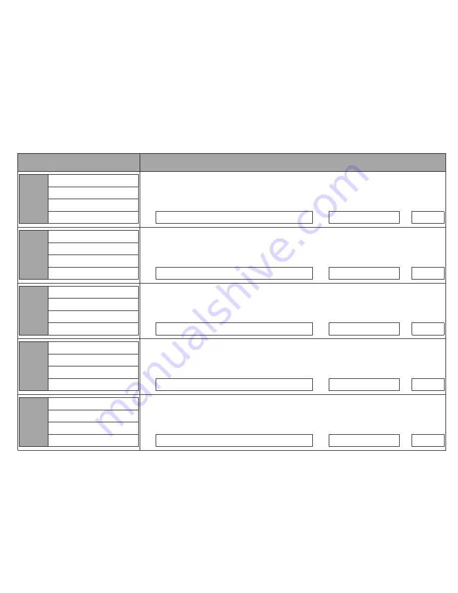
PNU Number
PNU Name
PNU Format
PNU Note
Range
1 ( 1 hex ) 1s
-
300 ( 12C hex ) 300s
Default
5 ( 5 hex ) 5s
Type
Read/Write
PNU Number
PNU Name
PNU Format
PNU Note
Range
20 ( 14 hex ) 20ms
-
800 ( 320 hex ) 800ms
Default
160 ( A0 hex ) 160ms
Type
Read/Write
PNU Number
PNU Name
PNU Format
PNU Note
Range
0 ( 0 hex ) 0 - 10V
-
1 ( 1 hex ) 4 - 20mA
Default
0 ( 0 hex ) 0 - 10V
Type
Read/Write
PNU Number
PNU Name
PNU Format
PNU Note
Range
0 ( 0 hex ) Off
-
999 ( 3E7 hex ) End of list
Default
0 ( 0 hex ) Off
Type
Read/Write
PNU Number
PNU Name
PNU Format
PNU Note
Range
0 ( 0 hex ) 0%
-
16384 ( 4000 hex ) Max value %
Default
0 ( 0 hex ) 0%
Type
Read/Write
9088 ( 2380 hex )
Allows the selected function to be scaled
Scaling Level
The output will change in proportion with the selected function
16 bit unsigned
The output will be at a maximum when the selected function equals the "Scaling Level"
Linear Scaling ( 1 = 0.006104 % )
9024 ( 2340 hex )
Allows the Analogue output to be mapped to different PNU functions
Select Function
The output will change in proportion with the selected function
16 bit unsigned
By default the output will be at a maximum when the selected function equals its maximum value
514=Imeasued, 522=Overload,
161=OverloadSCR, 542=Ptotal
8960 ( 2300 hex )
Defines the physical function of the analogue output (AO)
Analogue Output Type
0-10V : The output voltage varies from 0 to 10V
8 bit unsigned
4-20mA : The output current varies from 4 to 20mA
Binary value
8320 ( 2080 hex )
Time allowed for external contactors to close.
Contactor Delay
Increase if contactors are driven by buffer relays or motor trips on phase loss when start signal applied
16 bit unsigned
Decrease if response to start signal needs to be improved
Linear Scaling ( 1 = 1 ms )
7360 ( 1CC0 hex )
The time from the End of the start to the point where the iERS saving mode becomes active.
Dwell Time
Normally set to 5 seconds to ensure the motor is at full speed before the iERS saving becomes active
16 bit unsigned
Increase to allow time for the motor to stabilise.
Linear Scaling ( 1 = 1 s )
MAN-SGY-012-V11 EC 5195
Fairford Electronics Ltd - Synergy Modbus RTU Programming Manual - 22nd February 2016
Page 10 of 59