EXPERT Standard Series User Manual
124
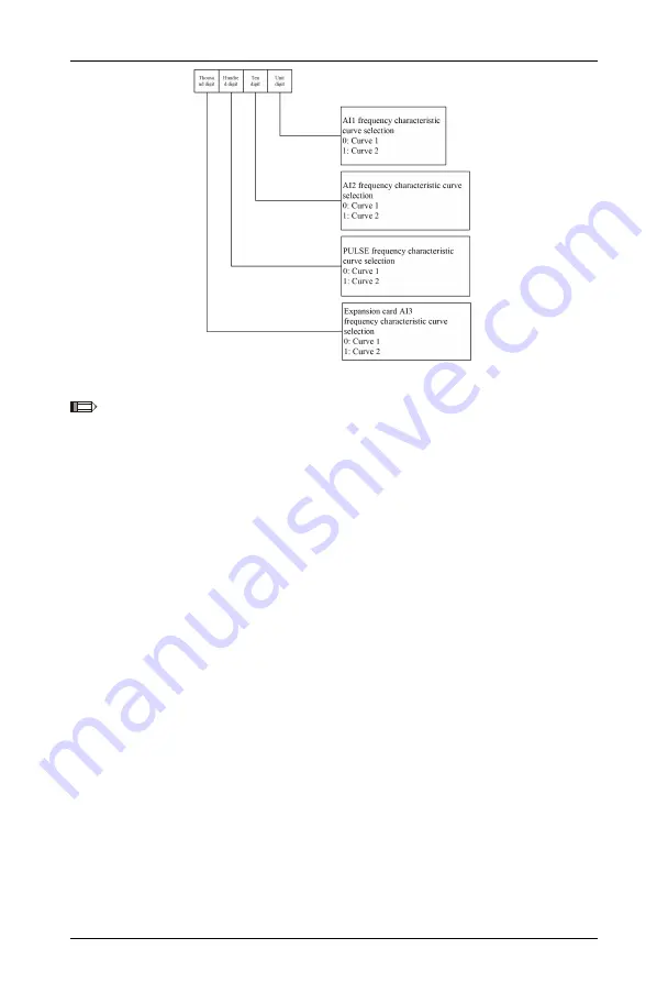
Figure 6-19 Frequency Given Curves
Note: For curve 3 and 4 function codes, refer to group A0 parameters.
Taking requirement analysis as an example:
① Use the pulse signal input from the terminal to set the given frequency;
② The input signal range is: 1kHz~20kHz;
③ The set frequency corresponding to 1kHz input signal is 50Hz, and the set
frequency corresponding to 20kHz input signal is 5Hz;
According to the above requirements, the parameter settings are as follows:
① F1.02 = 5, use the terminal PULSE given as the frequency given channel;
② F6.06=45, input pulse signal from DI4 terminal;
③ F5.00=100, select curve 2;
④ F5.03=20.0kHz, set the maximum pulse input frequency to 20kHz;
⑤ F5.08=1÷20×100%=5.0%, set the minimum given of curve 2 as the percentage of
1kHz to 20kHz(F5.03);
⑥ F5.09=50.00Hz, set the set frequency corresponding to the minimum given (1kHz
pulse signal);
⑦
F5.10=20÷20×100%=100.0%, set the maximum given of curve 2 as the
percentage of 20kHz to 20kHz(F5.03);
⑧ F5.11=5.00Hz, set the set frequency corresponding to the maximum given (20kHz
pulse signal);


