


EXPERT Standard Series User Manual
189
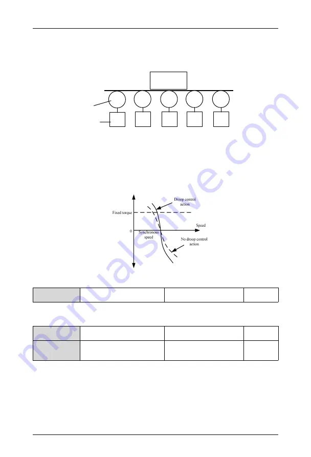
This function is suitable for the occasions where multiple drives drive the same load.
By setting this function, multiple drives can reach a uniform distribution of power when
driving the same load. For example, the transmission gears shown in Figure 6-60 (5 drives
drive the conveyors of 5 motors)
变频器
电机
传送带
1
2
3
4
5
负载
Figure 6-60 Droop Control Schematic Diagram
When the load of a certain drive is heavy, the drive will automatically reduce the output
frequency appropriately according to the parameters set by this function to unload part of
the load. This value can be adjusted gradually from small to large during debugging. The
relationship between load and output frequency is shown in Figure 6-61:
Figure 6-61 Droop Control Motor Characteristics
FC.11
Acceleration/deceleration
smoothing filter coefficient
0.1~100.0
1.0
The smaller this value, the slower the acceleration changes and the longer the actual
acceleration time.
FC.12
Zero frequency operation
threshold
0.00~550.0Hz
0.00Hz
FC.13
Zero
frequency
return
difference
0.00~550.0Hz
0.00Hz
These two function codes are used to set the zero frequency return difference control
function.
Analog AI2 given channel is taken as an example, as shown in figure 6-62:
Start process:
After a run command is sent, the motor starts only when analog AI2 input reaches or
exceeds a certain value Ib, and its corresponding set frequency reaches fb, and the motor
Motor
Conveyor
Load
Drive


