


- 44 -
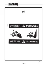
DANGER!!!
PERICOLO!!!
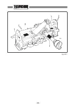
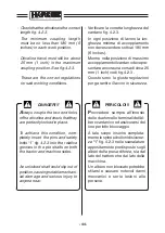
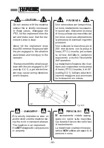
- Verificare la corretta lunghezza del
cardano fig. 4.2.3.
In ogni posizione di lavoro la lun-
ghezza minima di accoppiamento
non deve scendere sotto ai 180 mm
(6 inches).
Mentre nella posizione di massimo
accoppiamento il cardano deve pre-
sentare ancora una corsa di circa 25
mm (1 inch) vedi fig. 4.2.3.
Queste sono le giuste regolazioni
per garantire il lavoro in sicurezza.
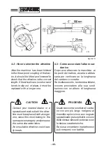
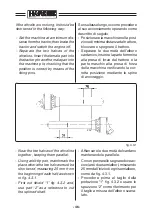
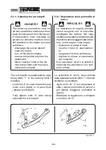
- Check that the driveline is the correct
length fig. 4.2.3.
The minimum coupling length
must be no less than 180 mm (6
inches) in each work position.
Driveline travel must still be about
25 mm (1 inch) in the maximum
coupling position. See fig. 4.2.3.
These are the correct regulations
for safe working conditions.
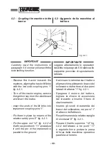
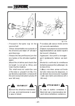
A
lways couple the two end forks
of the driveline and check that they
are perfectly locked in place.
To achieve this condition, com-
pletely insert the pins and safety
bolts “1” fig. 4.2.3 into the relative
grooves in the pto shafts on both
the tractor and machine sides.
An unlocked shaft could slip out of
position, causing notable mechani-
cal damage and serious injury to
anyone near.
P
rovvedere sempre all’innesto
delle due forcelle terminali dell’al-
bero cardanico ed assicurarsi del
loro perfetto bloccaggio.
A tale scopo inserire completa-
mente le spine e i bulloni di sicurez-
za “1” fig. 4.2.3 nelle scanalature
appositamente predisposte sugli
alberi della presa di forza, sia dal
lato del trattore che dal lato della
macchina.
Un albero non bloccato potrebbe
sfilarsi e causare notevoli danni
meccanici e serie lesioni alle
persone.
Summary of Contents for HARDEE HT3
Page 2: ......
Page 22: ...10...
Page 27: ...15 39914100 g 2 2 1 g 2 2 2 Z11 399143000 g 2 2 4 Z13 Z14 g 2 2 3 399CEE001 399CEE002 Z12...
Page 42: ...30 g 2 9 1 Z06...
Page 43: ...31 1 g 2 9 2 399CEE001 39914100 Z11 Z12...
Page 44: ...32 g 2 9 3 2 72 0386 00...
Page 45: ...33 3 g 2 9 4 72 0390 00...
Page 46: ...34 5 g 2 9 5 72 0391 00...
Page 50: ...38...
Page 98: ...86...
Page 106: ...94...
Page 107: ...95 9 Assembly instructions for Kit standing jack Schema di montaggio per Piedino di appoggio...
Page 108: ...STANDING JACK PIEDISTAL STUTZHALTER PIEDINO DI APPOGGIO HT2 1 10 12 11 4 5...
Page 110: ...7 3 6 2 4 5 STANDING JACK PIEDISTAL STUTZHALTER PIEDINO DI APPOGGIO HT3...
Page 112: ...7 12 12 8 10 9 11 6 STANDING JACK PIEDISTAL STUTZHALTER PIEDINO DI APPOGGIO HT4...
Page 114: ...STANDING JACK PIEDISTAL STUTZHALTER PIEDINO DI APPOGGIO HT6 7 11 11 8 10 9 12 6...
Page 116: ...STANDING JACK PIEDISTAL STUTZHALTER PIEDINO DI APPOGGIO HT9 8 13 13 9 11 10 12 7...
Page 118: ......
Page 119: ......


