


- 3 -
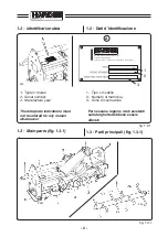
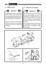
Legenda parti principali fig. 1.3.1
1-
Attacco a tre punti di aggancio della
macchina al trattore.
2-
Protezione albero presa di forza.
Impedisce il contatto da parte
dell’operatore con la parte rotante
dell’albero cardanico inserito nella
presa di forza.
3-
Gruppo riduttore.
Riduce la velocità di rotazione
della presa di forza del trattore
(P.T.O.).
4-
Trasmissione del moto al rullo
rotore.
Mediante la catena di trasmissione
il moto in uscita dalla scatola in-
granaggi viene trasferito al rotore
“7”.
5-
Telaio.
E’ la struttura portante della mac-
china.
6-
Rullo livellatore (optional).
Regola la profondità di lavoro degli
utensili.
Alcune versioni possono essere
dotate, in alternativa, di ruote po-
steriori aventi la stessa funzione
del rullo livellatore.
In alternativa le zappatrici sono
equipaggiate con slitte laterali "10"
la cui funzione oltre quella di rego-
lare la profondità di lavoro (come
il rullo livellatore) è di protezione
laterale.
Key to the main parts in fig. 1.3.1
1-
Three-point linkage used to couple
the implement to the tractor.
2-
Pto shaft guard.
Prevents the user from coming into
contact with the rotating part of the
driveline engaged in the pto.
3-
Gearbox.
Reduces the rotation speed of the
tractor pto.
4-
Drive transmission to the rotor
shaft.
Drive output from the gear box is
transferred to rotor “7” by means
of the transmission chain.
5-
Chassis.
This is the bearing structure of the
implement.
6-
Levelling roller (optional).
Adjusts the work depth of the
tools.
As an alternative, some versions
can be equipped with rear wheels
that act in the same way as the
levelling roller.
In alternative, the rotary tillers can
be equipped with side skids "10".
Besides adjusting the work depth
(as the levelling roller), these also
act as a side protection.
Summary of Contents for HARDEE HT3
Page 2: ......
Page 22: ...10...
Page 27: ...15 39914100 g 2 2 1 g 2 2 2 Z11 399143000 g 2 2 4 Z13 Z14 g 2 2 3 399CEE001 399CEE002 Z12...
Page 42: ...30 g 2 9 1 Z06...
Page 43: ...31 1 g 2 9 2 399CEE001 39914100 Z11 Z12...
Page 44: ...32 g 2 9 3 2 72 0386 00...
Page 45: ...33 3 g 2 9 4 72 0390 00...
Page 46: ...34 5 g 2 9 5 72 0391 00...
Page 50: ...38...
Page 98: ...86...
Page 106: ...94...
Page 107: ...95 9 Assembly instructions for Kit standing jack Schema di montaggio per Piedino di appoggio...
Page 108: ...STANDING JACK PIEDISTAL STUTZHALTER PIEDINO DI APPOGGIO HT2 1 10 12 11 4 5...
Page 110: ...7 3 6 2 4 5 STANDING JACK PIEDISTAL STUTZHALTER PIEDINO DI APPOGGIO HT3...
Page 112: ...7 12 12 8 10 9 11 6 STANDING JACK PIEDISTAL STUTZHALTER PIEDINO DI APPOGGIO HT4...
Page 114: ...STANDING JACK PIEDISTAL STUTZHALTER PIEDINO DI APPOGGIO HT6 7 11 11 8 10 9 12 6...
Page 116: ...STANDING JACK PIEDISTAL STUTZHALTER PIEDINO DI APPOGGIO HT9 8 13 13 9 11 10 12 7...
Page 118: ......
Page 119: ......


