Safety Circuit
Instruction Manual ATS 400 with SC-NG
Version 4.03
26
PIN
Notation
Description
5
E2WL1
Input 2 for the warning lamp 1 (red)
6
WL2(gn)
Output for warning lamp 2 (green)
7
E1WL2
Input 1 for the warning lamp 2 (green)
8
GND
Ground
9
O3
Output for the supply of the first monitoring element
10
O2
Output for the supply of the second monitoring element
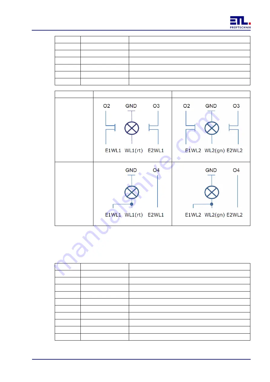
Monitoring
Warning lamp 1 (red)
Warning lamp 2 (green)
Monitored
Not monitored
7.5
Socket safety circuit
The connection of the safety circuit is a 10-pin LEMO PKG.M1.0NL.LN socket with a
coding of 0 ° and a black marking.
PIN
Notation
Description
1
O1
Output 1
2
O2
Output 2
3
O3
Output 3
4
E4
Input 4
5
E5
Input 5
6
E6
Input 6
7
E7
Input 7
8
E8
Input 8
9
Vcc
Supply
10
GND
Ground


