


Configuration
Hardware Manual • Doc. No.: V.1915.23/ Rev. 1.0
VME-PMC-CADDY/2plus
Page 20 of 47
3. PCB View with Coding Switches and Connectors
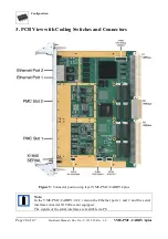
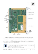
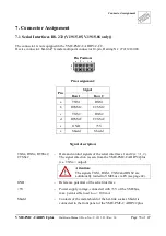
Figure 5: Connector position top layer VME-PMC-CADDY/2plus
Note:
In the VME-PMC-CADDY/2-CC version the Ethernet ports 1 and 2 and the serial
interface connector X1940 are not equipped.
The signals of the serial interface are available via P0.


