


Bootloader
Hardware Manual • Doc. No.: V.1915.23/ Rev. 1.0
VME-PMC-CADDY/2plus
Page 32 of 47
6.4 Flash Update
The bootloader resides at the top of the VME-PMC-CADDY/2plus onboard NOR flash memory.
Assuming a binary size of up to 512 kByte (0x7FFFF) the bootloader image must be programmed into
the flash memory starting at 0xFFF00000. Please check that you are using the correct bootloader image
that suits to your board! The bootloader update process is very delicate. Any mistake may result in a
board that is not usable anymore and which must be shipped back to be reprogrammed by esd using a
JTAG debugger.
Here are step-by-step instructions for bootloader update at the serial console. The tftp command
requires a correct U-Boot network configuration. That means the the bootloader environment variables
ipaddr, netmask, gatewayip and serverip must be set up according to your network.
When any of the following step fail, do not proceed! See chapter “Booting VxWorks”.
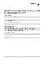
1. Upload the new bootloader binary image into RAM (e.g. at RAM address 0x1000000). The easiest
way is to load the images from a TFTP-server:
úû
üýüþ
ÿ888888
üýüþü
888
þ
Do not proceed if this step has failed!
If the upload has failed verify the IP address of server and board. Verify the Configuration of the TFTP-
server. Verify the access rights of the image file.
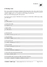
2. Remove flash write protection:
úû
þüü
ýý
88888
3. Erase the current bootloader. Attention: do not switch of the board from now on until a new
bootloader has been written into the flash!
úû
88888
4. Copy the new bootloader into flash:
úû
þ
ý
88888
ý
This command copies
ý
bytes starting at RAM location {filesize} into flash memory
starting at 0xFFF00000.
5. Enable flash write protection for bootloader address range:
úû
þüü
88888
6. When all the above commands succeeded reset the board.
úû
ü


