


Configuration
Hardware Manual • Doc. No.: V.1915.23/ Rev. 1.0
VME-PMC-CADDY/2plus
Page 24 of 47
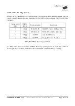
3.2.2 VMEbus System Controller Setup
This bits define how and whether the VME-PMC-CADDY/2plus is activated as VMEbus system
controller.
Coding switch-
contact 2
Coding switch
contact 1
Function
SCONEN#
SCONDIS#
OFF
OFF
Auto SCON: automatic activation of the system
controller (depending of signal VBG3IN#))
ON
OFF
System controller activated
OFF
ON
System controller deactivated
ON
ON
not allowed
Table 8: VMEbus system controller activation
Value of the parameter bits:
ON: Bit = ‘0’
OFF: Bit = ‘1’
For further information about the system controller functions please refer to chapter “System Controller
(SCON)”in the user manual of the Tsi148™ PCI/X-to-VMEbus Bridge [1].


