Connector Assignment
VME-PMC-CADDY/2plus
Hardware-Manual • Doc.-No.: V.1915.23 / Rev. 1.0
Page 35 of 47
k
l
m
n
o
p
q
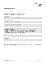
7. Connector Assignment
7.1 Serial Interfaces RS-232 (V.1915.05, V.1915.06 only))
The connector is not equipped in the VME-PMC-CADDY/2-CC.
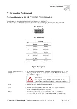
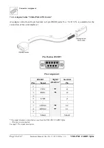
Device connector: har-link
®
female multipoint connector 10-pin, Harting Nr.: 27211218000
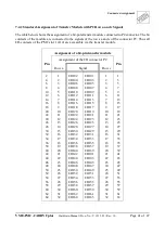
Pin Position:
Pin Assignment:
Pin
Signal
Row 1
Row 2
a
TXS1
RXS1
b
RTSS1#
CTSS1#
c
TXS2
RXS2
d
RTSS2#
CTSS2#
e
GND
+5V
z
Shield
Shield
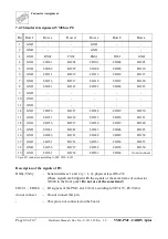
Signal description:
TXSx, RXSx, RTSSx#,
CTSSx#
...
Data and control signals of the serial interfaces 1 and 2 (x = 1, 2).
The signal direction is seen from the VME-PMC-CADDY/2plus
(i.e. TXSx = output).
Attention:
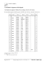
The signals TXS1, RXS1, TXS2 and RXS2 are
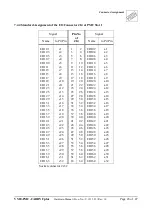
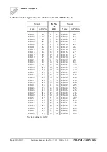
additionally routed to VMEbus via P0 (see page 42).
GND
...
Reference potential of the serial interface
+5V
...
Power supply voltage, connected with +5V of the VMEbus,
max. permissible load I
Load
< 100 mA
Shield
...
Contacts of the metal shield of the har-link socket. Shield is
connected to the front panel of the VME-PMC-CADDY/2plus .

