Overview
Hardware Manual • Doc. No.: V.1915.23/ Rev. 1.0
VME-PMC-CADDY/2plus
Page 14 of 47
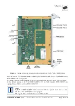
1.4.4 PMC-Slots
PMC-Standard
IEEE Std 1386-2001, IEEE Std 1386.1-2001
Equipment
two single-size modules
VME-PCI-Bridge
Tsi148
I/O-Signals
to VMEbus P2
and P0
Standard: according to VITA 35 (P4V2-64ac, P4V0-46), i.e.
PMC slot 1 (J14) completely to P2 row a and c,
PMC slot 2 (J24) completely to VMEbus connector P0
Signal voltage
level
3.3 V
Note:
In the state of delivery the VME-PMC-CADDY/2plus
and the VME-PMC-CADDY/2plus-T are equipped
with the SMD-resistors RX2530 to RX2535. Thus the
3.3 V supply is generated onboard form the +5V power
supply.
Optionally the 3.3 V can be supplied directly via the
VMEbus, if the SMD-resistors RX130 to RX135 are
equipped instead of the SMD-resistors RX2530 to
RX2535. Please contact our support before you order
this version.
In the VME-PMC-CADDY/2-CC version the 3.3 V has
to be supplied directly via the VMEbus because in this
version the SMD-resistors RX130 to RX135 are
equipped instead of the SMD-resistors RX2530 to
RX2535 per default.


