


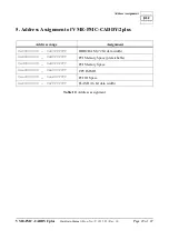


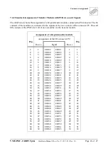
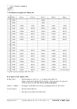
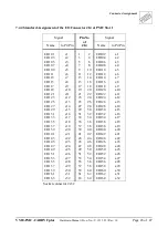
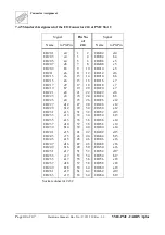


Connector Assignment
Hardware Manual • Doc. No.: V.1915.23/ Rev. 1.0
VME-PMC-CADDY/2plus
Page 36 of 47
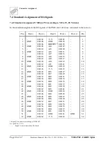
r
s
t
u
v
w
x
y
z
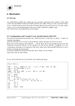
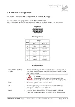
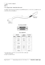
7.1.1 Adapter Cable “VME-PMC-CPU/Cable”
An adapter cable from 10-pin har-link to 9-pin DSUB (order No.: V.1917.25). is available for the
connection of the serial interface 1.
Pin Position DSUB9:
Pin Assignment:
DSUB9
Signal
direction *
har-link
Pin
Signal
Pin
1
-
-
2
TXS1
{
a1
3
RXS1
|
a2
4
-
-
5
GND
e1
6
-
-
7
CTSS1#
|
b2
8
RTSS1#
{
b1
9
-
-
-
Shield
Shield
* The signal direction is described as seen from the VME-PMC-CADDY/2plus .
-... This pin is not connected.
See page 35 for signal description.


