Overview
VME-PMC-CADDY/2plus
Hardware-Manual • Doc.-No.: V.1915.23 / Rev. 1.0
Page 9 of 47
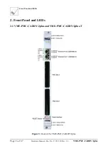
The front panel of the VME-PMC-CADDY/2plus has two cutouts for the front panels of the PMC
modules. A blank cover for unused slots is included in delivery.
Example libraries for the initialization of the board in C source code for VxWorks is available for a fee
on a disk. Drivers for other operating systems are available on request. Please state your operating
system with the version number when you order.
1.3 Hardware Configurations
Note:
All options given below have to be specified when ordering. They can not be installed
later. For order information see page 46.
1.3.1 I/O-Pin Routing
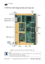
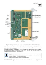
In the standard configuration VME-PMC-CADDY/2plus each of the I/O-pins of the PMC slot 1 (J14)
is connected to exactly one pin of the VMEbus connector P2 (according to VITA 35 (P4V2-64ac)) and
each of the I/O-pins of the PMC slot 2 (J24) is connected with exactly one I/O-pin of the VMEbus
connector P0 (according to VITA 35 (P4V0-64)). Other options are available on request.
1.3.2 Option “-T”: Extended Temperature Range
The VME-PMC-CADDY/2plus-T is designed for extended temperature range of -40
C ...+75
C.
1.3.3 Option: “-CC”: Conduction Cooled
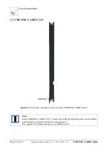
The VME-PMC-CADDY/2-CC is designed with covering heat sinks for heat dissipation in conduction
cooled systems. The PMC slots are for conduction cooled PMC modules.
As a result of the heat sinks the front panel and with it the 10-pin har-link
®
-connector with the serial
interfaces are not equipped. Furthermore the Ethernet interfaces and the front panel LEDs are not
equipped.
The conduction cooled version VME-PMC-CADDY/2-CC is designed for operation in the extended
temperature range from -40
C ...+75
C as the VME-PMC-CADDY/2plus-T version.


