SmartEdge 600 Router Hardware Guide
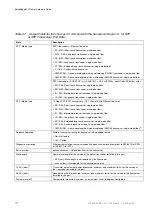
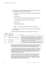
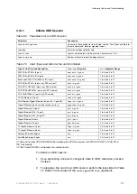
Table 71
Prepare a Line Card for an ODD Session
Task
Command
Notes
Access global configuration mode.
configure
Enter this command in exec mode.
Specify the card to be tested and access card
configuration mode.
card
Specify the card type and slot number.
Save the state of the ports and circuits on the card
and put it in the out-of-service state.
shutdown
If there are cross-connected circuits configured
on any of the ports on an ATM or Ethernet card,
this command disables the cross-connections
and saves their state.
Put the card in the ODD state.
on-demand-diagnostic
Commit the previous commands to the database and
return to exec mode.
end
You must enter this command to place the card
in the ODD state.
3.
To test one or more components, enter one of the commands listed in
Table 72; all commands are entered in exec mode. Table 69lists the values
for the
level-num
and
loop-num
arguments. The arguments
slot
,
slot1
,
slot2
, and
slotn
are chassis slot numbers for the line cards to be tested.
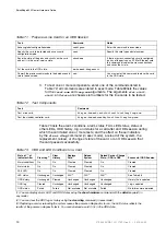
Table 72
Test Components
Task
Command
Test a line card.
diag on-demand card
slot
level
level
loop
loop-num
Test the standby controller card.
diag on-demand standby level
level
loop
loop-num
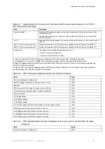
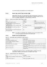
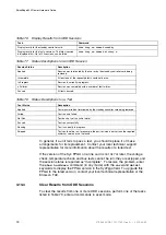
Table 73 lists the alarm conditions, alarm status, FAIL LED status, status of
other LEDs, ODD history, log, and status for a card after an ODD session during
which the card failed one or more tests; and the affect on these indicators
by the
clear diag
command (in exec mode), a reload of the system, the
replacement, reload, or change of state of the card, or an ODD session that
the card passed successfully.
Table 73
ODD and LED Conditions for a Card
State of
(1)
of
Indicator After
Clear Log
(2)
Clear
History
Replace
Card
(3)
Reload
System
Reload Card or Change
State—ODD to OSS
Successful ODD Session
Alarm conditions
On
On
Cleared
Cleared
On
Cleared
Alarm status
On
On
Cleared
Cleared
On
Cleared
FAIL LED
On
On
Cleared
Cleared
On
Cleared
LED status
Unchanged
Unchanged
N/A
(3)
(3)
N/A
(3)
See Table 68
ODD history
Unchanged
Cleared
Unchanged
Unchanged
Unchanged
History file is updated
ODD log
Cleared
Unchanged
Unchanged
Unchanged
Unchanged
Log is updated
ODD status
Failed
Failed
Not available
Not available
Failed
No failures were detected
(1) You can display alarm, LED, and ODD states using the
show hardware
command with the
detail
keyword (in
any mode).
(2) You can clear the ODD log or history using the
clear diag
command (in exec mode).
(3) Replacing a card or reloading the system causes the power-on diagnostics to run; the LED status reflects the
results of the power-on diagnostic tests. You cannot reload a card if it is in the ODD state.
84
27/153 30-CRA 119 1170/1 Uen A
|
2010-04-09
Summary of Contents for SmartEdge 600
Page 1: ...SmartEdge 600 Router Hardware Guide Release 6 3 INSTALLATION 27 153 30 CRA 119 1170 1 Uen A ...
Page 6: ...SmartEdge 600 Router Hardware Guide 27 153 30 CRA 119 1170 1 Uen A 2010 04 09 ...
Page 26: ...SmartEdge 600 Router Hardware Guide 20 27 153 30 CRA 119 1170 1 Uen A 2010 04 09 ...
Page 108: ...SmartEdge 600 Router Hardware Guide 102 27 153 30 CRA 119 1170 1 Uen A 2010 04 09 ...
Page 112: ...SmartEdge 600 Router Hardware Guide 106 27 153 30 CRA 119 1170 1 Uen A 2010 04 09 ...

