SmartEdge 600 Router Hardware Guide
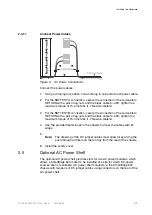
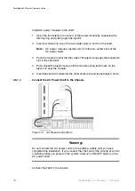
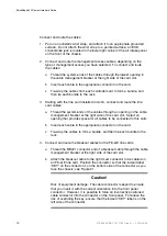
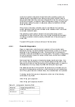
13. Power on the chassis by connecting the AC power cords to separate 220
VAC building outlets, each of which must be for a circuit rated at 20A with a
20A circuit breaker.
Note:
The AC power cords ship with North American plugs installed. If
you are connecting to another type of service, simply remove the
plugs and replace them with the appropriate plugs.
14. Check the status LEDs located on the alarm card at the front of the chassis
and the AC input power and DC output power LEDs on the front of each
installed power module.
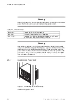
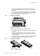
If you encounter problems installing the AC power shelf, contact your local
technical support representative.
2.6
Card Slots
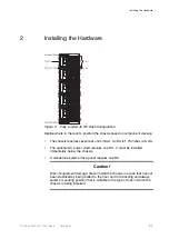
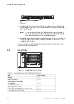
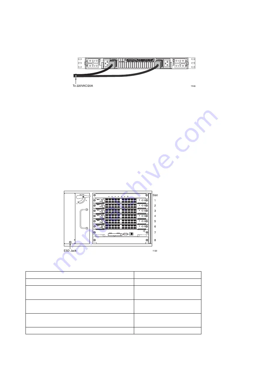
Figure 11
SmartEdge 600 Card Slots
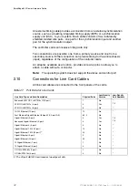
Table 25
Slot Assignments for SmartEdge 600 Cards
Card
Slots Available
Controller
7, 8
ATM OC-12c/STM-4c
ATM OC-3c/STM-1c (any version)
1 to 6
10/100 Ethernet
Fast Ethernet–Gigabit Ethernet
1 to 6
20-port Gigabit Ethernet 1020
(1)
Transceiver-based Gigabit Ethernet (any other version)
1 to 5
1 to 6
OC-192c/STM-64c (any XFP version)
1 to 6
32
27/153 30-CRA 119 1170/1 Uen A
|
2010-04-09
Summary of Contents for SmartEdge 600
Page 1: ...SmartEdge 600 Router Hardware Guide Release 6 3 INSTALLATION 27 153 30 CRA 119 1170 1 Uen A ...
Page 6: ...SmartEdge 600 Router Hardware Guide 27 153 30 CRA 119 1170 1 Uen A 2010 04 09 ...
Page 26: ...SmartEdge 600 Router Hardware Guide 20 27 153 30 CRA 119 1170 1 Uen A 2010 04 09 ...
Page 108: ...SmartEdge 600 Router Hardware Guide 102 27 153 30 CRA 119 1170 1 Uen A 2010 04 09 ...
Page 112: ...SmartEdge 600 Router Hardware Guide 106 27 153 30 CRA 119 1170 1 Uen A 2010 04 09 ...

