background image

APPENDIX B  CREATING PROCEDURE OF ASSEMBLY SOURCE FILE (Sub tool chain)

S5U1C88000C MANUAL II

EPSON

255

WORKBENCH/DEV TOOLS/OLD ASSEMBLER

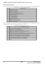
B.3.6 Source File Insertion Pseudo-Instruction [sap88 only]

Source file insertion pseudo-instruction is a pseudo-instruction to read and insert other files into the
optional location of source file.

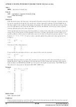
INCLUDE

*

This instruction can only be used in the structured preprocessor sap88. The sap88 expands this instruc-
tion and creates the source file in which the specified file is inserted. In the cross assembler asm88, this
instruction cannot be used and will cause an error if used.

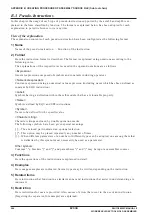
Name:

INCLUDE

.....Another file insertion

Format:

INCLUDE    <file name>

Functions:

This instruction reads the specified file in the following an INCLUDE statement.
Including can be nested to optional depths. Another file can be further included into a file that is
already included.

The sap88 analyses this pseudo-instruction and creates the output file in which the specified file is
inserted. This pseudo-instruction is not transferred to the asm88 as is.

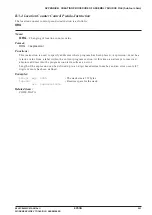
Examples:

include chargen.s

;

Character generator

include utilsub

;

General purpose subroutine group

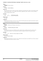
Limitation:

This instruction can only be used in the structured preprocessor sap88. In the cross assembler asm88,
it cannot be used and will cause an error if used.

Summary of Contents for S1C88 Series

Page 1: ... Integrated Tool Package for S1C88 Family CMOS 8 BIT SINGLE CHIP MICROCOMPUTER S5U1C88000C Manual II Workbench Development Tools Assembler Package Old Version ...

Page 2: ...ranty that anything made in accordance with this material will be free from any patent or copyright infringement of a third party This material or portions thereof may contain technology or the subject relating to strategic products under the control of the Foreign Exchange and Foreign Trade Law of Japan and may require an export license from the Ministry of Economy Trade and Industry or other app...

Page 3: ...ification Package D die form F QFP B BGA Model number Model name C microcomputer digital products Product classification S1 semiconductor Development tools S5U1 C 88348 D1 1 Packing specifications 00 standard packing Version 1 Version 1 Tool type Hx ICE Ex EVA board Px Peripheral board Wx Flash ROM writer for the microcomputer Xx ROM writer peripheral board Cx C compiler package Ax Assembler packa...

Page 4: ......

Page 5: ...ent Describes the Work Bench that provides an integrated development environment Advanced Locator the Mask Data Creation Tools Development Tool Chain part shown in the figure on the next page Debugger and Structured Assembler Sub Tool Chain part shown in the figure on the next page This manual assumes that the reader is familiar with C and Assembly languages Refer to the following manuals as neces...

Page 6: ...n file file CMP file SPJ Component mapping file Simulator project file model PAR ICE parameter file model MOT Peripheral circuit board FPGA data ice88ur ini ICE ini file file BMP Bitmap file LCD panel customize utility LcdUtil exe file Axx Result data file file CSV Check sheet file file Mxx Reference data file file TXT Command file Auto evaluation system AutoEva exe file SY Symbolic table file Sym...

Page 7: ... 5 3 Source Menu 14 3 5 4 Build Menu 14 3 5 5 Debug Menu 14 3 5 6 Tools Menu 14 3 5 7 Help Menu 15 3 6 Project and Work Space 16 3 6 1 Creating a New Project 16 3 6 2 Inserting Sources into a Project 17 3 6 3 Removing a Source from the Project 17 3 6 4 Project View 17 3 6 5 Opening and Closing a Project 18 3 6 6 Saving the Project 18 3 7 Creating Editing Source Files 19 3 7 1 Specifying an Editor ...

Page 8: ...il88xxx 51 7 4 Error Messages 52 7 5 Example of Input output Files 53 CHAPTER 8 FUNCTION OPTION GENERATOR winfog _______________________ 54 8 1 Outline of winfog 54 8 2 Input output Files 54 8 3 Using winfog 55 8 3 1 Starting Up 55 8 3 2 Window 56 8 3 3 Menus and Toolbar Buttons 57 8 3 4 Operation Procedure 58 8 4 Error Messages 61 8 5 Example Output Files 62 CHAPTER 9 SEGMENT OPTION GENERATOR win...

Page 9: ...gger 88 13 3 1 Starting the Debugger 88 13 3 2 Terminating the Debugger 89 13 4 Windows 90 13 4 1 Basic Structure of Window 90 13 4 2 Command Window 91 13 4 3 Source Window 93 13 4 4 Dump Window 98 13 4 5 Register Window 99 13 4 6 Symbol Window 99 13 4 7 Watch Window 99 13 4 8 Trace Window 100 13 4 9 Coverage Window 100 13 5 Menu 101 13 6 Tool Bar 105 13 7 Method for Executing Commands 106 13 7 1 ...

Page 10: ... 13 9 7 Break 156 bp software breakpoint set 156 bpa software area breakpoint set 158 bpr bc bpc software breakpoint clear 160 bas sequential break setting 161 ba hardware breakpoint set 162 bar hardware breakpoint clear 164 bd hardware data breakpoint set 165 bdr hardware data breakpoint clear 167 bl breakpoint list 168 bac break all clear 169 13 9 8 Program Display 170 u unassemble 170 sc source...

Page 11: ...Program Development Procedures 205 A 2 1 Development Flow 205 A 2 2 Creating Source File 207 A 2 3 Assembly 210 A 2 3 1 Structured preprocessor sap88 210 A 2 3 2 Cross assembler asm88 210 A 2 3 3 Starting sap88 and asm88 212 A 2 3 4 Batch processing for relocatable assembly ra88 bat 214 A 2 3 5 Relocatable object file 218 A 2 3 6 Assembly list file 218 A 2 3 7 Cross reference list 219 A 2 3 8 Erro...

Page 12: ... Notation 243 B 3 Pseudo Instructions 244 B 3 1 Section Setting Pseudo Instructions 245 B 3 2 Data Definition Pseudo Instructions 247 B 3 3 Symbol Definition Pseudo Instructions 251 B 3 4 Location Counter Control Pseudo Instruction 253 B 3 5 External Definition and External Reference Pseudo Instructions 254 B 3 6 Source File Insertion Pseudo Instruction sap88 only 255 B 3 7 Assembly Termination Ps...

Page 13: ...f all files as a project execution of make process invocation of tools includ ing the editor specified by the user Supports C and S1C88 Family assembly languages This package contains C compiler tools as well as the conventional structured assembler tools Supports simulator auto evaluation system and ICE as debugging tools The work bench invokes the ICE S5U1C88000H5 an optional development tool fo...

Page 14: ... file file CMP file SPJ Component mapping file Simulator project file model PAR ICE parameter file model MOT Peripheral circuit board FPGA data ice88ur ini ICE ini file file BMP Bitmap file LCD panel customize utility LcdUtil exe file Axx Result data file file CSV Check sheet file file Mxx Reference data file file TXT Command file Auto evaluation system AutoEva exe file SY Symbolic table file Symb...

Page 15: ...e a load module that has abso lute address This file is used for debugging and creating mask data Advanced locator alc88 exe Realizes the locator s relocation functions without using description files in DELFEE Moreover it incorporates a new function that helps to optimize branching See Chapter 5 for details about ad vanced locator The tools available in the Main tool chain except advanced locator...

Page 16: ...to create the mask data file that will be presented to Seiko Epson Refer to Chapters 6 through 12 for details of the tools in the Development tool chain Debug tool db88 debugger ice88ur exe Controls the ICE S5U1C88000H5 provided as a hardware tool for the S1C88 Family to debug pro grams Commands that are used frequently such as break and step are registered on the tool bar minimizing the necessary...

Page 17: ...ompatibles that can run the system software listed below A personal computer using Pentium 200 MHz or greater as the CPU and incorporating 64 MB or more of RAM is recom mended Installation requires a CD ROM drive To use the optional ICE S5U1C88000H5 the personal computer also requires a USB port and Win dows 2000 or Windows XP Display A 800 600 dots display unit or higher is required System softwa...

Page 18: ...g box 4 Click on the Next button to proceed Choose Destination Location A dialog box for specifying the folder in which to install the tools appears 5 If you do not wish to change the default settings simply click the Next button to execute installa tion To install in another folder Click Browse to bring up the Choose Folder dialog box From this dialog box enter the path or select the folder in wh...

Page 19: ...maintainer PR88 EXE Object reader SY88 EXE Symbolic table file generator ICE88UR EXE S5U1C88000H control software ICE88UR HLP S5U1C88000H help file Other related files SAP S1C88 Family Structured Assembler Tools SAP88 EXE Preprocessor ASM88 EXE Assembler LINK88 EXE Linker HEX88 EXE HEX converter REL88 EXE Symbol information generator SYM88 EXE Symbolic table file generator DB88 DB88 debugger direc...

Page 20: ...ents of the sample programs WRITER 8xxxx Flash microcomputer name URW2 RW8xxxxx EXE Universal ROM Writer II control software 8xxxxx FRM Firmware OBPW OBW8xxxx EXE On board Programming ROM Writer control software RW8xxxx INI Device information setup file MPRW G8xxxxxx EXE Multiple Programming ROM Writer control software Refer to the technical manual for details of the ROM Writer and PROM programmin...

Page 21: ... supports tag jump from error messages using a user s editor Allows simple management of all necessary files and information as a project General make process to invoke necessary tools and to update the least necessary files Supports all options of the S1C88 Family C compiler tool chain and invocation of each tool Windows GUI interface for simple operation 3 2 Starting Up and Terminating the Work ...

Page 22: ...ow is configured with Project view Option view and Message view Menu bar Toolbar Option view Project view Message view Status bar Each view area can be resized by dragging the boundary A standard scroll bar appears if the display contents exceed the view area Use it to scroll the display contents The arrow keys can also be used ...

Page 23: ...tion The option view changes its display contents according to the selection in the project view whether node or file as well as clicking a tool name tab Refer to Section 3 9 for details Message view This area displays the messages delivered from the executed tools in a build or compile process Double clicking a syntax error message with a source line number displayed in this window invokes the sp...

Page 24: ...ton Compiles or assembles the source file selected in the option view according to the source format Build button Builds the currently opened project using a general make process Rebuild button Builds the currently opened project All the source files will be compiled assembled regardless of whether they are updated or not Stop Build button Stops the build process being executed BMPUtil button Invo...

Page 25: ... When a file name is entered in the displayed dialog box the specified editor activates and opens a new document The created source file is inserted into the currently opened project Header Files node in the project view New Project Creates a new project Open Ctrl O Opens a source file header file or project file A dialog box will appear allowing selection of the file to be opened When a source or...

Page 26: ...d Builds the currently opened project using a general make process ReBuild All Builds the currently opened project All the source files will be com piled assembled regardless of whether they are updated or not Stop Build Stops the build process being executed 3 5 5 Debug Menu SIM88 Simulator Invokes the Sim88 simulator DB88 Debugger Invokes the db88 debugger ICE88UR Debugger Invokes the ice88ur de...

Page 27: ...hecker Invokes the mask data checker winmdc On Board ROM Writer Invokes the on board ROM writer control software Sim88 Configuration Displays a dialog box for setting the path to the simulator Sim88 exe Editor Configuration Displays a dialog box for setting the editor path and the command line options 3 5 7 Help Menu About WB88 Displays a dialog box showing the version of the work bench ...

Page 28: ... the following folders in the folder If a folder which has the same name as that of a specified one already exists in the specified location the work bench uses the folder as the work space The specified project name will also be used for the absolute object and other files Folders created in the work space def Folder in which advanced locator definition files and various other definition files ar...

Page 29: ...ource file or header file is created with this menu command the file is automatically added to the project that is currently open For more information on creating new source and header files refer to Section 3 7 2 The newly created files are added to the project and displayed in the Project view 3 6 3 Removing a Source from the Project To remove a source or header file from the project select the ...

Page 30: ... Close Workspace from the File menu At this time a dialog box appears to select whether the current project file is to be saved or not if it has not already been saved after a modification If Yes save is selected in this dialog box all the modification items includ ing file configuration and tool settings will be saved 3 6 6 Saving the Project To save the currently edited project file select Save ...

Page 31: ...figuration dialog box shown below is displayed Enter the following information in this dialog box Editor Path Enter the path to the editor used or select an editor from the file select dialog box displayed by clicking the Reference button Parameter Enter the normal representation of command line options to specify a file name and line number for tag jump when invoking the editor The f and l are re...

Page 32: ...C source file is selected Leave it checked to copy code from the C startup module stationery file into the C source file to be created The stationery file is cstart c in the EPSON S1C88 LIB SRC folder 2 Click the OK button This creates a specified source file and the selected editor starts to open that file The created file is also added to the project tree displayed in the Project view 3 In the e...

Page 33: ...double click the message to open the relevant source file in the editor and to jump to the source line with the error WB88 xxxxxxx xxxxxx Double click the error message Shows the line with the error xxxx xxxxx xxxx xxxxx Editor Tag jump Note Before using the tag jump function you must ascertain that your editor supports command line based tag jumps and that the command line option is correctly set...

Page 34: ...ts in the work space the corresponding C source file is not compiled to reduce process time Likewise the assembler is invoked to generate relocatable object files Next the linker is invoked to generate an absolute object file Finally the advanced locator or the locator is invoked to generate an executable object file To rebuild all files including the latest assembly source and relocatable object ...

Page 35: ... Editor for details about and how to create definition files 3 8 3 Running only the Compiler or Assembler The source files can also be compiled or assembled individually To invoke only the compiler or assem bler select the source file to compile or assemble from the Project view then select Compile Assemble from the Build menu or click the Compile Assemble button Compile Assemble button Depending ...

Page 36: ...ng on the selection made in the Project view as shown below 1 Select a project name Linker options are displayed 2 Select Source Files C Default compile options which apply to all C sources are displayed 3 Select a C source file Local compile options which apply only to the selected C source are displayed 4 Select Source Files ASM Default assemble options which apply to all assembly sources are di...

Page 37: ... displayed by clicking the button Merge C source Code with Assembly Output s option of c88 If this option is selected C source codes are merged with the assembler output before being output Enable Symbolic Debug Information g option of c88 If this option is selected symbolic debug information is included in the output file Set Optimization O option of c88 Selecting this option specifies O1 to opti...

Page 38: ... that are not displayed The C compiler options not displayed in the Option view are handled as described below e This option is used in internal processing err C compiler messages are displayed in the message window and output to an error log file f file This option conflicts with internal processing and cannot be used o file The source file name is also used for the output file V This option is n...

Page 39: ...ded before assembly You can also select the files to include from the dialog box displayed by clicking the Reference button Default Label Identifiers i l g option of as88 Specify the default label style as local or global Select from the pull down list Generate Listing File l option of as88 If this option is selected the assembler generates a list file Contents L option of as88 This button is enab...

Page 40: ...rocessing err Assembler messages are displayed in the Message window and output to an error log file f file This option conflicts with internal processing and cannot be used o file The source file name is also used for the output file V This option is not used in wb88 v This option is not used in wb88 c Specify this option in the linker option setup screen M s c d l Specify this option in the link...

Page 41: ...ent variable C88LIB is searched To search other directories enter the appropriate path in Additional Search Path or select a directory from the list displayed by clicking the Reference button Warning Level w n option of lk88 Specify the level to which to suppress warning messages Levels 0 to 9 can be selected from the pull down list The default setting is 8 Warning messages whose levels are higher...

Page 42: ...s automatically processed internally in accordance with memory model settings and system library search settings O file File names are set to the project name o file File names are set to the project name u symbol To specify this option enter it in Other Options V This option is not used in wb88 3 9 4 Locator Options This screen can be used to select the following options Warning Level w n option ...

Page 43: ...ton in this dialog box to stop build ing or rebuilding a project If this dialog box need not be displayed click the Disable Build States Message check box Space Name for Specific Output S space option of lc88 Enter a space name here the locator then generates a specific output file corresponding to the speci fied space Other options To specify other options including those listed above enter the d...

Page 44: ...description file dsc The default is _START which can suffice when starting from cstart c When starting from another C routine set a function name prefixed by _ when starting from an assembler routine set the symbol name of that routine Example 1 Assembler routine GLOBAL _main When starting from _main set _main 2 C routine When starting from void main set _main Add Symbol Rom Set the name and addre...

Page 45: ... size of memory or a device to be connected to the external bus of the microcom puter The items to be set in the respective lines are described below Addr Enter the start address of external memory or a device Mem Choose the type of external memory from the pulldown list Rom ROM Ram RAM Dev Any memory mapped device e g LCD controller Size Enter the capacity of external memory or the mapped size of...

Page 46: ... Chip Mode list 3 Enter a start symbol name in Start Symbol as necessary Normally leave _START intact 4 Enter the location addresses of sections etc in the Add Symbol Rom and Add Symbol Ram boxes How to enter will be detailed later 5 To use external memory or a device enter the related information in the Add External Memory box How to enter will be detailed later 6 Select the Disable branch optimi...

Page 47: ...or quitting wb88 To delete the addresses set in Add Symbol Rom Ram 1 Delete all contents of Addr Name and Kind on the address line you want to delete by using the Backspace or Delete key and selecting blank for Kind 2 When three cells have been blanked click the Enter key The line will be deleted with subsequent lines moved up Add External Memory Defining and deleting external memory For systems t...

Page 48: ...ing a project stop saving a project or quitting Note that wb88 does not check input content for whether the addresses you have entered are within the implemented memory area or whether there are any duplicate symbol names Such discrepancies or errors are checked by alc88 or lc88 3 About sections generated by the compiler When user defined successive sections are to be specified in Add Symbol Rom R...

Page 49: ...e part xxxxx 5 Operations for deselecting the Disable Making DELFEE check box while currently selected Selecting this check box automatically selects the Disable branch optimize check box for locator options While in this state the Disable Making DELFEE check box cannot be deselected again To deselect this check box while it currently is selected first deselect the Disable branch optimize check bo...

Page 50: ...anual Setting the path to the simulator Before simulator sim88 can be invoked you must set its path To set the path select Sim88 Configura tion from the Tool menu to display the dialog box shown below Select sim88 exe from the dialog box that is displayed by clicking the button or enter a path directly into the text box Once a path is set there is no need to set it again the next time the simulato...

Page 51: ...etting utility PrtUtil CMP File Editor specified with Tool Editor Configuration FSA File Function option generator winfog see Chapter 8 For detailed information on the LCD panel customize utility and port setting utility refer to the simulator manual These tools can also be launched from the Tool menu or with the toolbar button 3 Using the Load module format radio button select the object file for...

Page 52: ...ton DB88 button To start the ice88ur debugger select ICE88UR Debugger from the Debug menu or click the ICE88UR button ICE88UR button The dialog box shown below is displayed 4 Using the Load module format radio button select the absolute object file format IEEE 695 or Motorola S 5 In Fsa File specify a function option HEX file This is done by selecting a file from the file select dialog box display...

Page 53: ...ator 6 Mask data checker 7 On board ROM writer control software Menu item Tool Simulator Tools Auto Evaluation System Tool Simulator Tools Bitmap Utility Tool Simulator Tools LCD Panel Customize Utility Tool Simulator Tools Port Setting Utility Tool Dev Tools Function Option Generator Tool Dev Tools Mask Data Checker Tool On Board ROM Writer Button For information on how to use each tool refer to ...

Page 54: ...ion Project name makefile Project name Source name reference Source name reference Source name reference Option Project name Project name Project name Model name Model name Model name Model name Project name Project name Project name Project name Project name Model name Option Option Option Option Option Option Option Option Option sim88 debug Option Model name Model name ice88ur Extension c h c a...

Page 55: ...lename The file is already existed in the project It cannot be added in the project filename WB88 does not support such source file type filename Description The file filename cannot be added to the project because it is not a C source file The file filename cannot be added to the project because it is not an assembly source file The file filename cannot be added to the project because it is not a...

Page 56: ...odule to generate one new relocatable object file 4 Locator lc88 exe Relocates the relocatable object created by lk88 to absolute addresses of memory to generate an executable load image file The relocation information to be referenced at this time must be written in DELFEE language in the locator description files that are loaded on the locator Note that lc88 can be used to develop applications u...

Page 57: ...red for alc88 Instead alc88 uses the advanced locator definition file inf that can be easily generated by the section editor functions of wb88 without any specific concern about details Therefore you have the option of using lc88 when using conventional resources including locator definition files to develop applications or alc88 when developing new applications or not specifically requiring exist...

Page 58: ... it relocates relocatable objects to absolute addresses of memory The section editor of wb88 creates this file Absolute object file file abs This is an executable object file output from the relocatable objects supplied to alc88 by being relo cated to the absolute addresses of memory This file is created in IEEE 695 format and contains debugging information included in the input files Program data...

Page 59: ...al memory available for xxxx Duplicate Symbol Name xxxx Cannot find 0xnnnn bytes for xxxx section Found unresolved external xxxx There is no stack area Absolute address 0xnnnn occupied Value out of range to label xx at address 0xnn Description Advanced locator definition file inf is invalid Memory allocations in 0xnnnn 0xnnnn and 0xnnnn 0xnnnn are duplicated No specified addresses exist to which s...

Page 60: ...rocom puter for the three tools described above This file must be available before each tool can be executed 5 ICE parameter file 88xxx par This file is used to establish correspondence between the ICE and each type of microcomputer This file is required for starting up the ICE 6 Program unused area filling utility fil88xxx exe This tool extracts the built in ROM area from a program data HEX file ...

Page 61: ...elopment tools New peripheral board new development tools Old peripheral board new development tools New peripheral board old development tools S1C88832 862 s BZ R51 and TOUT R26 outputs Not available Available Not available Not considered a problem Not available Not considered a problem Variation of OSC1 3 oscillator frequencies OSC1 is for a CR oscillator OSC3 is for a CR or ceramic oscillator N...

Page 62: ...sk data checker zzzzzzzz sa Built in ROM data HEX file Motorola S2 format zzzzzzzz psa Fig 7 2 1 Input output files of fil88xxx Program data HEX file zzzzzzzz sa This is a Motorola S2 format program data HEX file generated by the HEX converter hex88 or a third party software tool Built in ROM data HEX file zzzzzzzz psa This is a Motorola S2 format file that contains the built in ROM data extracted...

Page 63: ...e When a series of operation are complete the fil88xxx displays the following message When terminated normally Indicates the proceeding status Unused Area Filling Completed System Area Data Set Completed The converted HEX file psa is generated in the same directory as the input file When an error has been occurred C8xxx0A0 SA 5 File Format Error Example of error message If an error is generated du...

Page 64: ...ss length is not 3 bytes including S1 S3 S7 and S9 record The check sum does not match There is a duplicate definition of data in the same address The physical address 0000xxH cannot be used as a vector because they are reserved as a system area for the S1C88xxx There is no disk space An error has occurred while writing data 1 A file format error will occur under the following conditions Another r...

Page 65: ...FFFFFFFFFFFFFFFFFFFFFFFFFFFFFFFFFFFFFFFFFFFF7B S2240000A0FFFFFFFFFFFFFFFFFFFFFFFFFFFFFFFFFFFFFFFFFFFFFFFFFFFFFFFFFFFFFFFF5B S2240000C0FFFFFFFFFFFFFFFFFFFFFFFFFFFFFFFFFFFFFFFFFFFFFFFFFFFFFFFFFFFFFFFF3B S2240000E0FFFFFFFFFFFFFFFFFFFFFFFFFFFFFFFFFFFFFFFFFFFFFFFFFFFFFFFFFFFFFFFF1B S224000100CF6E00F6B4FFDD0030DD0100D94004C700F0C40000CFDCC30200D700F8E7F7F262 S2240001209300D94004B0FFB104C543F8C700F8CFEB7...

Page 66: ...e Device information definition file To ICE Mask data creation by mask data checker s1c88xxx ini zzzzzzzz fsa zzzzzzzz fdc Fig 8 2 1 Input output files of winfog Device information definition file s1c88xxx ini This file contains option lists for various types of microcomputers and other information Always be sure to use the files presented by Seiko Epson This file is effective for only the type of...

Page 67: ... will then read the Device information definition file Startup by command input You can also start winfog from the MS DOS prompt by entering the command shown below winfog s1c88xxx ini denotes entering the return key You can specify the device information definition file s1c88xxx ini as a command option You can also specify a path When you specify the device information definition file here winfog...

Page 68: ...ndow is divided into three areas as shown above Option list area Lists mask options set in the device information definition file s1c88xxx ini Use the check boxes in this area to select each option A selected option has its check box marked by Function option document area Displays the contents of selected options in the function option document format The contents displayed in this area are outpu...

Page 69: ...ntents of the option list The Gener ate button has the same function Generate button Setup Sets the date of creation output file name and a comment included in the function option document file The Setup button has the same function Setup button Device INI Select Loads the device information definition file s1c88xxx ini The Device INI Select button has the same function This file must be loaded fi...

Page 70: ... device information definition file is selected the same file is automatically loaded the next time you start winfog Note When you load a device information definition file after setting up options all settings are reset to the default state 2 Setup Select Setup from the Tool menu or click the Setup button to bring up the Setup dialog box From this dialog box select items and enter data Setup butt...

Page 71: ...o the following limitations 1 The number of characters that can be used to specify a file name including the path is 2 048 2 The file name itself not including the extension can be up to 15 characters and the exten sion up to three characters 3 The file name cannot begin with a hyphen nor can the following symbols be used as part of directory names folder names file names and extensions The symbol...

Page 72: ... loaded If the specified file exists and there is no problem with its contents the option list and the function option document areas are updated according to the contents of the file To stop loading the file click Cancel Perform steps 2 to 4 to update the file If you select Generate without changing the file name the message shown below is displayed asking you whether or not to overwrite the file...

Page 73: ... Description Number of characters in the file name or extension exceeds the limit Prohibited characters have been entered File name has not been entered File xxxx cannot be opened Specified device information definition file ini does not exist Specified device information definition file ini does not contain function option information Specified function option document file does not exist Content...

Page 74: ...R 200KHz Selected OPT0201 01 OPTION NO 3 INPUT PORT PULL UP RESISTOR K00 With Resistor Selected K01 With Resistor Selected K02 With Resistor Selected K03 With Resistor Selected K10 With Resistor Selected K11 With Resistor Selected K12 With Resistor Selected K13 With Resistor Selected OPT0301 01 OPT0302 01 OPT0303 01 OPT0304 01 OPT0305 01 OPT0306 01 OPT0307 01 OPT0308 01 OPTION NO 4 OUTPUT PORT OUT...

Page 75: ...of mask options zzzzzzzz sad zzzzzzzz sdc winsog Segment assignment data file Segment option document file Function option document file zzzzzzzz ssa Segment option HEX file To ICE Mask data creation by mask data checker zzzzzzzz fdc Device information definition file s1c88xxx ini Fig 9 2 1 Input output files of winsog Device information definition file s1c88xxx ini This file contains option lists...

Page 76: ...ile as it starts Alternatively drag the device information definition file icon into the winsog exe icon to start winsog which will then read the device information definition file If a function option document file is required for setting the segment option a dialog box will appear to allow file selection In this case enter the file name including the path in the text box or choose the file from ...

Page 77: ...H DEV TOOLS OLD ASSEMBLER When winsog starts it displays the SOG window The following diagrams show a SOG window when the device information definition file has been loaded and when it has not SOG Window initial screen SOG Window after reading the device information definition file ...

Page 78: ...ry addresses and segment configuration vary with each type of microcomputer Fig 9 3 2 1 Window configuration The SOG window is divided into two areas as shown above Option setup area Comprised of a display memory map a segment decode table and buttons to select pin specifications By clicking on cells in the display memory map and segment decode table you can assign display memory addresses and bit...

Page 79: ...has the same function Load button End Terminates winsog Tool menu Generate Creates a file according to the contents of segment options set The Generate button has the same function Generate button Setup Sets the date of creation or output file name or a comment included in the segment option document file The Setup button has the same function Setup button Device INI Select Loads the device inform...

Page 80: ...icking the Ref button Click OK and the file is loaded If the specified file exists and there is no problem with its contents the set up items in winsog are initialized with the loaded device information To stop loading the file click Cancel 9 3 4 Option Selection Buttons The following buttons are available in the option setup area OUTPUT Option buttons These buttons select SEG pin output modes The...

Page 81: ... Specify the segment option document file name you want to create The file name displayed by default can be modified You can use the Ref button to look at other folders Segment Option HEX Do you make hex file Select whether to create a segment option HEX file You need to create one when you use the ICE to debug programs Segment Options HEX file When you create a segment option HEX file specify its...

Page 82: ...f directory names folder names file names and extensions The symbols shown below cannot be used in the User s Name and Comment 3 Setting segment outputs The LCD drive circuit of a S1C88 Family chip that has had segment options set normally allows selecting the segment output and DC output for every two pins in certain types of microcomputers individually for each pin Segment output should be speci...

Page 83: ...pin is unused leave it blank Selection example 4 Setting DC outputs When using SEG pins for general purpose DC output assign segments according to steps 1 and 2 described in Item 3 Setting segment outputs However output control works in such a way that the display memory assigned to COM0 is enabled while the display memory assigned to COM1 through COM3 are disabled Therefore set a memory address d...

Page 84: ...You can save the segment option settings that have not been completed as a segment assignment data file To save data select Record Save from the File menu or click the Save button Save button The dialog box shown below appears so enter a file name including the path in the text box or select a file by clicking the Ref button Clicking OK saves the current assignment data to the specified file To st...

Page 85: ...T DECODE TABLE are updated according to the contents of the file To stop loading the file click Cancel If you want to change an assigned address clear its cell assignment using the Delete button first and then reassign a new address If you want to change a selected output mode too select the correspond ing SPEC cell and clear its selected output mode with the Delete button before reselecting a new...

Page 86: ...r extension exceeds the limit Prohibited characters have been entered File name has not been entered File xxxx cannot be opened Specified device information definition file ini does not exist Specified device information definition file ini does not contain segment option information Specified function option document file does not exist Contents of the specified function option document file do n...

Page 87: ... a segment assignment data file S1C88xxx SEGMENT OPTION DOCUMENT Vx xx Version FILE NAME zzzzzzzz SDC File name specified by Setup USER S NAME User name specified by Setup INPUT DATE yyyy mm dd Date of creation specified by Setup COMMENT Comment specified by Setup OPTION NO xx Option number varies with type of microcomputer LCD SEGMENT DECODE TABLE SEG COM0 COM1 COM2 COM3 SPEC 0 163 162 161 1F3 S ...

Page 88: ...e the files presented by Seiko Epson This file is effective for only the type of microcomputer indicated by the file name Do not modify the contents of the file or use the file in other types of microcomputers Built in ROM data HEX file zzzzzzzz psa This is the built in ROM data HEX file in Motorola S2 format This file is created by program unused area filling utility fil88xxx The unused areas in ...

Page 89: ...nition file Startup by command input You can also start winmdc from the MS DOS prompt by entering the command shown below winmdc s1c88xxx ini denotes entering the return key You can specify the device information definition file s1c88xxx ini as a command option You can also specify a path When you specify the Device information definition file here winmdc reads it as it starts This specification c...

Page 90: ... button has the same function Pack button Unpack Restores files in the original format from a packed file The Unpack button has the same function Unpack button Device INI Select Loads the device information definition file s1c88xxx ini The Device INI Select button has the same function This file must be loaded first before performing any operation with winmdc Device INI Select button Help menu Ver...

Page 91: ...ton The dialog box shown below appears Enter a file name including the path in the text box or select a file by clicking the Ref button Click OK and the file is loaded If the specified file exists and there is no problem with its contents the set up items in winmdc are initial ized with the loaded device information To stop loading the file click Cancel Once a device information definition file is...

Page 92: ...Ref button to look at other folders Make sure the extension of the output file name is pa0 If after presenting data to Seiko Epson you present new data due to program bugs or any other reason increase the number in the last digit of the extension in increments of one For example the extension of the second file presented should be c88xxx yyy pa1 Note File name specification is subject to the follo...

Page 93: ...pe specified in the device information definition file by their default file names Modify the file name displayed by the following procedure a Click in the list box to select the file name to be modified b Click the Ref button to select another folder and then enter a file name Modify all the listed file names The extensions cannot be changed 4 Click the Unpack button to execute unpacking When win...

Page 94: ...line Checksum does not match Data is large Greater than ROM size Data is small Smaller than ROM size Start mark is incorrect End mark is incorrect Model name shown at the beginning of data is incorrect Display Message Message Message Message Message Message Message Message Message Message Table 10 4 3 List of function option data error messages Message Option data error Illegal model name Option d...

Page 95: ...option start mark S1C88xxx FUNCTION OPTION DOCUMENT V x x Model name version FILE NAME zzzzzzzz FDC USER S NAME SEIKO EPSON CORPORATION INPUT DATE yyyy mm dd COMMENT SAMPLE DATA zzzzzzzz fdc OPTION NO 1 OSC1 SYSTEM CLOCK Crystal 32 768KHz Selected OPT0101 01 OPTnn01 01 EOF END Function option end mark SEGMENT1 Segment option start mark S1C88xxx SEGMENT OPTION DOCUMENT Vx xx Model name version FILE...

Page 96: ...5 Segment option document file t88xxx sdc This is the document file corresponding to the segment option HEX file shown above and is generated by winsog Note that the segment option files 4 and 5 are provided for only certain types of microcomputers that have set segment options 6 readme txt This file contains the description of the S5U1C88xxxP LED illumination status to check the operation with th...

Page 97: ...rd memory U User memory S Stack area W Write protect Default does not protect Internal ROM Map0 000000 00EFFF E W 5 Internal RAM Map1 00F000 00F3FF E Stack area Map2 00F400 00F5FF E S Display memory Map3 00F800 00F828 I Map4 00F833 00F842 I Map5 00F900 00F928 I Map6 00F933 00F942 I Map7 00FA00 00FA28 I Map8 00FA33 00FA42 I Map9 00FB00 00FB28 I Map10 00FB33 00FB42 I Map11 00FC00 00FC28 I Map12 00FC...

Page 98: ... an area is specified without the W switch the ICE will regard it as a RAM area Comments The ICE identifies a line that begins with a semicolon as a comment line Comments cannot be placed following parameters Example Internal ROM OK Map0 000000 00EFFF EW internal ROM NG 12 3 Emulation Memory The ICE has built in a 64KB emulation memory for the memory space from 000000 to 00FFFF and a 512KB emulati...

Page 99: ...2 1 Input output files Parameter file file_name par This text file contains memory information on each microcomputer model and is used to set the memory mapping information to the ICE For the contents of this file refer to Chapter 12 88xxx par File Absolute object file file_name abs This is an IEEE 695 object file generated by the advanced locator or locator By reading a file in this format that c...

Page 100: ...ting and Terminating the Debugger 13 3 1 Starting the Debugger Connect the ICE S5U1C88000H5 to a personal computer and turn the power on before starting up the debugger The debugger can be started up using one of the following methods Starting from Work Bench After the build process of the project has completed select DB88 Debugger from the Debug menu or click the DB88 button The dialog box shown ...

Page 101: ... position and size of the windows will return the same as the last time the debugger was terminated Note If the ICE is in self diagnosis state when the ICE is turned on with the DIAG switch set to on position the debugger does not display OK until the diagnosis is finished The self diagnosis takes about 40 seconds for the process If NG is displayed restart the debugger after checking the following...

Page 102: ... uses the window for displaying the executed results To close a window click the Close box on the window The opened windows are listed in the Window menu Selecting one from the list activates the selected window It can also be done by simply clicking on an inactive window Furthermore pressing Ctrl Tab switches the active window to the next open window 2 Resizing and moving a window Each window can...

Page 103: ...plays command execution results However some command execution results are displayed in other windows The contents of these execution results are displayed when their corresponding windows are open If the corresponding window is closed the execution result is displayed in the Command window When writing to a log file the content of the write data is displayed in the window Refer to the description...

Page 104: ...tring those commands are listed Then when another character string is entered one of the recently executed commands among those listed is selected highlighted that includes the character string If the command history contains only a single command registered that begins with the character string the command is pasted directly into the prompt position If the command history does not contain any com...

Page 105: ...w or run the sc command When an absolute object file abs that contains C source debug information is loaded while the Source window is open the Source window auto matically enters this mode In this display mode the source file name is displayed on the title bar Source button 3 Mix display mode In this mode the debugger displays the source and its disassembled contents address code and mnemonic sep...

Page 106: ...d and executed g gr s n se or rst command or the memory contents are changed de df or dm command the display contents are updated In this case the Disassemble window updates its display contents so that the current PC address can always be displayed 2 Displaying the current PC The current PC program counter address is indicated by a yellow arrow at the beginning of the line 3 Displaying PC breakpo...

Page 107: ...d in the following manner as well as by scrolling Select a function name from the Functions pulldown list The source is displayed from the beginning of that function Click the Current PC button The source is displayed from the current PC address To display another source file click the Source Files button to bring up the dialog box shown below and to select the desired source file from the list of...

Page 108: ... 5 Searching for a character string In source display mode the Source window displays the following find buttons permitting a search for a character string Click the Find button to display the dialog box shown below allowing you to specify a search string Enter a search string in the Find what edit box and click the Find Next button The string search proceeds in the downward direction of the Sourc...

Page 109: ...ers the member s variable name needs to be selected with the mouse For array elements variable names must be selected with the mouse Out of scope variables are not displayed Mix display mode The mix display mode is functionally the same as disassemble display mode The difference is that each source line and the disassembled contents of the corresponding object code physical logical address object ...

Page 110: ...f or dm command or by direct modification After executing the program g gr s n se or rst command the display contents are also updated To refresh the Dump window manually execute the dd command or click the vertical scroll bar After program execution is completed the value changed during execution is displayed in red 2 Direct modification of data memory contents The Dump window allows direct modif...

Page 111: ...ame directory as the target program file Note that a symbol file is not read when an IEEE 695 program file is loaded 13 4 7 Watch Window The window shows the name and the current value of the symbol registered using the w command or the Source window Watch button The value is displayed in the format specified by the w command If the symbol is an array structure or union a icon is displayed Clickin...

Page 112: ...e cleared when the target program is executed After the execution has finished the Trace window displays the contents of the trace buffer 13 4 9 Coverage Window This window shows the coverage information executed address information acquired by the ICE The displayed contents indicate the memory map in 16 bytes per line The value at the beginning of each line is a physical address hexadecimal value...

Page 113: ...s to break must be clicked Go after Reset This button resets the CPU and then executes the target program after fetching the reset vector It performs the same function when the gr com mand is executed Step This menu item executes one instruction step at the address indicated by the current PC The F11 key can also be used It performs the same function when the s command is executed Next This button...

Page 114: ...log box for setting a software break enable area and sequential break mode Trace Menu Trace This menu item activates the Trace window to displays the trace informa tion sampled in the ICE trace data buffer It performs the same function as executing the td command Trace Search This menu item searches trace information from the trace data buffer under the condition specified using a dialog box It pe...

Page 115: ...the Trace window and displays the trace data sampled in the ICE trace data buffer Coverage This menu item opens or activates the Coverage window and displays the coverage information acquired in the ICE Symbol This menu item opens or activates the Symbol window and displays the symbol list if a symbol information has been loaded Watch This menu item opens or activates the Watch window and displays...

Page 116: ...LD ASSEMBLER Window Menu Cascade This menu item cascades the opened windows Tile This menu item tiles the opened windows This menu shows the currently opened window names Selecting one acti vates the window Help Menu About DB88 This menu item displays an About dialog box for the debugger ...

Page 117: ...rms the same function when the g command is executed Go to Cursor button This button executes the target program from the address indicated by the current PC to the cursor position in the Source window the address of that line Before this button can be selected the Source window must be open and the address line where the program is to break must be clicked Go after Reset button This button resets...

Page 118: ...existing data are specified a guidance mode is entered when only a command is input In this mode the system brings up a guidance field so input a parameter there Input example cmw File name test cmd Input data according to the guidance underlined part Commands requiring parameter input as a precondition The cmw command shown in the above example reads a program file into the debugger Commands like...

Page 119: ...ed string as a hexadecimal e g ABC However if the string includes other than the specified hexadecimal characters an error is assumed If the O1 option is specified when compiling the C source some symbols written in the source may not actually be used for reasons of code optimization In such cases debug information for that symbol is not output to the abs file whether or not the g option is specif...

Page 120: ...mmand file with wait Reset CPU Set clear software breakpoint Set sequential break mode Set clear hardware breakpoint Set clear data break conditions Break list Clear all break conditions Display trace information Search trace information Save trace information to file Display coverage information Clear coverage information Disassemble display Source display Mix display Dump memory Display register...

Page 121: ...ile name start cmd lf test abs bp 0004d7 g A command file to write the commands that come with a guidance mode can be executed In this case be sure to break the line for each guidance input item as a command is written Reading in and executing a command file The debugger has the com and cmw commands available that can be used to execute a command file The com command reads in a specified file and ...

Page 122: ...e log file Display of Command window in log mode The contents displayed in the Command window during log mode differ from those appearing in normal mode 1 When executing a command when each window is open When the window that displays the command execution result is opened Normal mode The contents of the relevant display window are updated The execution results are not displayed in the Command win...

Page 123: ...la S2 program file psa or a function option HEX file fsa The debugger distinguishes these files with the specified extension It is necessary to load an IEEE 695 absolute object file that contains debugging information to perform source level debugging The symbol file is required to specify addresses using the symbols defined in the source when debugging a Motorola S2 program file Debugging can be ...

Page 124: ... Disassemble display mode Source display mode and Mix display mode Table 13 8 2 1 Commands menu items tool bar buttons to switch display mode Function Disassemble display mode Source display mode Mix display mode Command u sc m Button Menu View Source Disassemble View Source Source View Source Mix 1 Disassemble display mode In this mode the debugger displays the program codes after disassembling i...

Page 125: ...defined in the source file can be used to specify an address This feature can be used when entering a command having address in its parameter from the Command window or a dialog box However the object file loaded must contain symbol information To perform symbolic debugging after loading a program file psa in the Motorola S2 format it is necessary to prepare a symbol file with the same name as the...

Page 126: ... memory The memory contents are displayed in a specified size Byte Word Long Float Double hexadecimal dump format If the Dump window is opened the contents of the Dump window are updated if not the contents of the data memory are displayed in the Command window 2 Entering modifying data Data at a specified address is rewritten by entering hexadecimal data Data can be directly modified on the Dump ...

Page 127: ...splaying registers Register contents and the contents of the memory specified in register indirect addressing can be displayed in the Register or Command window Registers PC SP IX IY A B H L BR CB NB EP XP YP SC I1 I0 U D N V C Z and CC F3 F2 F1 F0 Memory HL SP IX IY IX L IY L 2 Modifying register values The contents of the above registers can be set to any desired value The register values can be...

Page 128: ... Except being stopped by this temporary break the program continues execution until it is stopped by one of the following causes Break conditions set by a break set up command are met A break signal is input to the ICE BRKIN pin The Key Break button is clicked the Run Stop menu command is selected or the Esc key is pressed A program execution error is detected Key Break button When the program doe...

Page 129: ...o the higher level subroutine by a return instruction and is halted after returning At the highest level the program is executed in the same way as when run by the g command If a lower level subroutine is called and returned from it the program execu tion is not halted In either case the program starts executing from the current PC Table 13 8 4 2 Commands menu items tool bar buttons for single ste...

Page 130: ...4 3 External interrupt modes External interrupt halt and slp instructions Enable mode Interrupt is processed Executed as the halt instruction Processing is continued by an external interrupt or clicking on the Key Break button Disable mode Interrupt is not processed The halt and slp instructions are replaced with a nop instruction as the instruction is executed Run Monitor Interval Set the display...

Page 131: ...o measurements are made when single stepping a program Resetting the CPU Table 13 8 4 4 Commands menu items tool bar buttons for resetting CPU Function Reset CPU Successive execution after resetting CPU Command rst gr Button Menu Run Reset CPU Run Go after Reset The CPU is reset when the gr command is executed or by executing the rst command The following shows the initial settings when the CPU is...

Page 132: ...Software breakpoints can be set at up to 64 separate addresses and in one area with a specified address range However these breakpoints are effective in only a 1 MB active break area If any address outside this area is specified no breaks can occur at that address although the address is registered as an invalid breakpoint The 8 MB of code space is divided into eight 1 MB active break areas one of...

Page 133: ...th area size in bytes shown in the AreaNum column Setting a new area with a software break area already registered prompts a warning In such case delete the registered software break area before setting a new one Any address including those in a software break area can be registered only once as a breakpoint Neither addresses nor areas that contain a breakpoint address can be set twice or more as ...

Page 134: ...tual code generated Example 1 void func void NG 2 OK 3 int a NG 4 int x 0 OK 5 a x OK 6 OK Line 1 is a function declaration that does not have actual code same as a label declaration in the assembler A breakpoint cannot be set here Line 3 is a variable declaration that does not have actual code A breakpoint cannot be set here Line 4 is a variable declaration that has initialization code generated ...

Page 135: ...ified number of times Settings on BA1 and BA2 are not effective BA2 3 sequential mode In this mode program execution is made to break when the program has fetched the instruction at the address set on BA3 the specified number of times after executing the instruction more than once at the address set on BA2 Setting on BA1 is not effective BA1 3 sequential mode In this mode program execution is made...

Page 136: ...ready been registered as a hardware PC breakpoint will prompt a warning If addresses are set on each channel as shown above in BA1 3 sequential mode program execution is made to break after the program executes instructions at each set address as follows 1 Start running 2 Execute instruction at address 0x0003A5 once or more 3 Execute instruction at address 0x0003C0 once or more 4 Execute instructi...

Page 137: ...Select Breakpoint Setting from the Break menu to display the Break setting dialog box Select click the Hardware Data Break Setting tab in the dialog box Use the radio buttons to select the channel on which you want to set break conditions then enter an address in the Location at text box and data in the Data Value for text box optional Use the radio buttons to select the desired read write conditi...

Page 138: ... Run Stop menu command and ESC key can be used to forcibly termi nate the program being executed Key Break button Low level input to the ICE BRKIN pin By setting the BRKIN pin of the ICE to LOW a break occurs at the rising edge of the signal Break due to program execution error A break occurs when the ICE has detected one of the operations below during a program execution Writing data to the ROM a...

Page 139: ...n 8 192 cycles The trace data buffer is cleared when a program is executed starting to trace the new execution data The following lists the trace information that is taken into the trace data buffer in every instruction execution cycle This list is corresponded to display in the Trace window INS Executed cycle number 0 to 8191 decimal 0000 means oldest trace data P Addr PC address hexadecimal phys...

Page 140: ...ecify whether to trace both program fetch and data read write cycles or only data read write cycles Specify whether to trace either read or write cycles or both To set trace mode select Setting from the Break menu To set all trace mode select the All radio button and click OK To set range specified trace mode select the Range radio button then specify an address range by entering the start and end...

Page 141: ... the OK button When number entry is omitted the debugger assumes the start cycle number is 0 and the end cycle number is 0x1fff 8191 To cancel trace data display click the Cancel button It is possible to specify a search condition and display the trace information that matches a specified condition The search condition can be selected from the following three 1 Program s execution address 2 Addres...

Page 142: ...nction Save trace information Command tf Button Menu Trace Trace File When Trace File is selected from the Trace menu the dialog box shown below appears Enter the start and end cycle numbers of the range to be saved to the Start Point and End Point text boxes respectively Enter the file name to the File Name text box or choose a folder file using the Browse button Then click the OK button to start...

Page 143: ... set coverage options select Setting from the Coverage menu Enter a numeric value from 0 to 255 in the Coverage Area 0 255 text box to specify the desired acquisition range Use the radio buttons to select the desired acquisition mode Click the OK button to confirm what you ve set To stop setting coverage click the Cancel button The acquired coverage information can be displayed in the Coverage win...

Page 144: ...The accessed addresses are marked with an asterisk and addresses not accessed are marked with a space The Count value indicates the total addresses accessed in bytes among the 16 bytes on each line In addition to the Coverage window the executed addresses in the Source window are marked with an asterisk except in source display mode Executing the cv command while the Coverage window is closed disp...

Page 145: ...her model The debugger supports the following FPGA data handling functions 1 Erasing FPGA All contents of the FPGA are erased 2 Writing data to FPGA Data in the specified file is written to the FPGA Also the write command supports erasing the FPGA Data for the supported models are provided as c88xxx mot files in the epson s1c88 ice fpga directory default 3 FPGA data comparison The contents of the ...

Page 146: ...ve firmware clocks can be selected for the ICE 1 4 MHz selected by default 2 2 MHz 3 1 MHz 4 500 kHz 5 250 kHz The ICE uses the firmware clock to execute its debugging functions For example a memory dump is performed using the firmware clock Therefore if the target board you re using consists of a low speed device or one that may cause a delay in data output the memory dump contents and contents r...

Page 147: ...conditions Disassemble code display Source display Mix display Display symbol list Display symbol information Load program option HEX file Load parameter file Display trace information Search trace information Save trace information Display coverage information Clear coverage information Load and execute command file Load and execute command file with execution interval Record executed commands to...

Page 148: ... execution of the command Note Shows notes on using GUI utility Indicates a menu item or tool bar button if they are available for the command Notes In the command format description the parameters enclosed by indicate they are necessary parameters that must be input by the user while the ones enclosed by indicate they are optional parameters The input commands are case insensitive you can use eit...

Page 149: ...ress1 and address2 are not defined the Dump window is redisplayed beginning with address 0x000000 If address1 is defined the Dump window is redisplayed in such a way that address1 is displayed at the uppermost line Even when address1 specifies somewhere in 16 addresses line data is displayed beginning with the top of that line For example even though you may have specified address 0x00ff08 for ad ...

Page 150: ... Value 00FF00 30 00 00 FF FF FF FF FF FF FF FF FF FF FF FF FF 0 00FF10 00 00 1F 00 FF FF FF FF FF FF FF FF FF FF FF FF If size is defined in place of address2 the debugger displays the specified bytes of data from address1 dd ff00 20 Address 0 1 2 3 4 5 6 7 8 9 A B C D E F Value 00FF00 30 00 00 FF FF FF FF FF FF FF FF FF FF FF FF FF 0 00FF10 00 00 1F 00 FF FF FF FF FF FF FF FF FF FF FF FF 3 Displa...

Page 151: ...en When displaying data in the Command window data is displayed for the 16 lines following the previously displayed address same number of lines as displayed in the Dump window during log output dd Address 0 1 2 3 4 5 6 7 8 9 A B C D E F Value 000000 AE 02 F0 F0 C9 02 F0 F0 F0 F0 F0 F0 F0 F0 F0 F0 000010 00 A4 E0 48 0A 08 E0 80 EE 6A FC BA 3E BA 4A 01 H j J 0000F0 A6 A2 22 82 A0 0C 04 02 FE F7 BD ...

Page 152: ... Command is terminated Notes The start address specified here must be within the range of the memory area available with each microcomputer model An error results if the limit is exceeded or the input one is not a hexadecimal number or a valid symbol The contents of the unused area will be marked as If you encounter any address marked by press Enter key to skip that address or terminate the comman...

Page 153: ...ification of memory contents To modify data on the Dump window place the cursor at the front of the data to be modified or double click the data and then type a hexadecimal character 0 9 a f Data in the address will be modified with the entered number and the cursor will move to the next address This allows successive modification of a series of addresses ...

Page 154: ...ddress ff2ff End address is input Data pattern 0 Data is input Command execution can be canceled by entering only the Enter key and nothing else Notes Both the start and end addresses specified here must be within the range of the memory area available with each microcomputer model An error results if the limit is exceeded or the input one is not a hexadecimal number or a valid symbol An error res...

Page 155: ...dm ff200 100 ff280 Same as above Format 3 dm Start address ff200 Source area start address is input End address ff2ff Source area end address is input Destination address ff280 Destination area start address is input Command execution can be canceled by entering only the Enter key and nothing else Notes All the addresses specified here must be within the range of the memory area available with eac...

Page 156: ...ing the following symbols B for byte 1 byte default W for word 2 bytes L for long 4 bytes step Step in bytes in which increments to search equal to data size specified by size when omitted Condition 0 address1 address2 0xffffff address2 address1 0xffff byte 0x10000 1 step 0xffff Examples ds f000 30 W S 10 00F000 00F070 In this example the command searches for word data 0x0030 starting from address...

Page 157: ...dow is opened all the above contents are displayed in the Register window according to the program execution When you use the rd command the displayed contents of the Register window is updated 3 When Register window is closed Data is displayed in the Command window in the following manner rd PC 02AE SP AAAA IX AAAA IY AAAA B AA A AA H AA L AA BR AA CB 01 NB 01 EP 00 XP 00 YP 00 SC I1 I0 U D N V C...

Page 158: ... Z Old value value HL Old value value BR Old value value CB Old value value EP Old value value XP Old value value YP Old value value register Register name PC SP IX IY A B HL BR CB EP XP YP SC I1 I0 U D N V Z C value Value to be set to the register hexadecimal Examples Format 1 rs SC 0 Resets all the flags in the SC register Format 2 rs PC 02ae 180 SP aaaa f0ff IX aaaa f000 IY aaaa f000 A aa 0 B a...

Page 159: ...gal register name in direct input mode In guidance mode the following keyboard inputs have special meaning q Command is terminated finish inputting and start execution Return to previous register Input is skipped keep current value GUI utility Register window The Register window allows direct modification of data Click the Register window select the displayed data to be modified and enter a value ...

Page 160: ...ecution breaks the system stands by waiting for a command input after displaying the number of executed cycles execution time When you hit the Enter key here program execution is resumed beginning with the break address The break address setting is also valid 2 Window display by program execution The Source window is updated after a break in such a way that the break address is displayed within th...

Page 161: ...he address you specified must be within the range of the program memory area available with each microcomputer model An error results if the limit is exceeded or the input one is not a hexadecimal number or a valid symbol GUI utility Run Go menu item Go button When this menu item or button is selected the g command without break address specification is executed Go button Run Go to Cursor menu ite...

Page 162: ...s causes the PC to be set at the boot address from which the command starts executing the program Once the program starts executing the command operates in the same way as the g command except that the gr command does not support the function for restarting execution by hitting the Enter key Refer to the explanation of the g command for more information Note If a break condition is met program exe...

Page 163: ...nds by waiting for command input If you hit the Enter key here the system single steps the program in the same way again 2 HALT and SLEEP states and interrupts When the halt or slp instruction is executed the CPU is placed in standby mode An interrupt is required to clear this mode The debugger has a mode to enable or disable an external interrupt for use in a single step operation External interr...

Page 164: ...error results if the limit is ex ceeded If the Dump window is opened its display contents are updated after the execution The program will not break even if the break condition set by a command is met while this command is processed GUI utility Run Step menu item Step button When this menu item or button is selected the s command without step count is executed Step button ...

Page 165: ...me way as the s command However the call instructions including all subroutines until control returns to the next address are executed as one step Notes The step count must be specified within the range of 0 to 65 535 An error results if the limit is ex ceeded If the Dump window is opened its display contents are updated after the execution The program will not break even if the break condition se...

Page 166: ...program starts from the current PC address in single stepping and stops immediately after it returns to the caller routine Notes Do not execute the se command in the main top level routine If the Dump window is opened its display contents are updated after the execution During a single step operation the program will not break even if the break condition set by a command is met GUI utility Run Ste...

Page 167: ...RAM are not initialized at initial reset The respectively stipulated initializations are done for internal peripheral circuits Reset exception processing loads the preset values stored in 0 bank 000000H 000001H into the PC At the same time 01H of the NB initial value is loaded into CB If the Source window is open the window is redisplayed beginning with the boot address If the Register window is o...

Page 168: ... 8 MB of code space is divided into eight 1 MB active break areas one of which can be selected as a break option by using Break Setting At debugger startup a 1 MB area from 0x0 to 0x0fffff is automatically selected as the active break area Up to a total of 64 breakpoints can be set Any attempt to exceed this limit prompts a warning The addresses must be specified within the range of the program me...

Page 169: ...by an asterisk in the list select that address from the list by clicking the ON part then click the Disable button The asterisk disappears and the breakpoint is disabled To enable an invalid breakpoint select the address of that breakpoint from the list then click the Enable button The address is marked with an asterisk to indicate that a breakpoint is enabled at that address To clear a breakpoint...

Page 170: ...ugger s operating environ ment results in an error being assumed The 8 MB of code space is divided into eight 1 MB active break areas one of which can be selected as a break option by using Break Setting At debugger startup a 1 MB area from 0x0 to 0x0fffff is automatically selected as the active break area Only one software break area can be set at a time Before a new software break area can be se...

Page 171: ...etting a new area with a software break area already registered prompts a warning In such case delete the registered software break area before setting a new one Also note that because only one software break area can exist at a time any area that contains an address already registered as a breakpoint cannot be set as a software break area To disable a valid breakpoint whose address is preceded by...

Page 172: ...ll breakpoints and break area bpc Clears all breakpoints and break area Notes The bc and bpc commands have the same functions If no address parameter is specified for the bc or bpc command it works the same as the bpr com mand and all the breakpoints and break area that have been set are cleared An error results if an address that is not set at a breakpoint is specified GUI utility Break Breakpoin...

Page 173: ...ayed Independent Break Mode Notes Do not insert any space between bas and mode See the ba command for the operation in each mode and setting each break channel The debugger is configured to independent break mode at the time it starts up The set break conditions are all cleared when a program or a parameter file is loaded GUI utility Break Setting menu item When this menu item is selected a dialog...

Page 174: ... mode BAS3 In this mode program execution is made to break when the program has fetched the instruction as many times as set by count at the breakpoint set on CH3 after executing the instructions more than once in that order at the breakpoints set on CH1 and CH2 Format 1 ba channel address count direct input mode 2 ba channel option direct input mode channel Break channel number 1 3 address Break ...

Page 175: ...setting or clearing breakpoints Before performing any operation described below select the Hardware PC Break Setting tab Use the radio buttons to select the channel on which you want to set an address then enter the desired address in the Location at text box To specify an execution count on BA3 enter a hexadeci mal number for the desired count in the CH3 Count text box If a count was set from the...

Page 176: ...ars the hardware breakpoints that have been set and the CH3 counter Format bar direct input mode Example bar Clears all the hardware breakpoints set Note An error results if no hardware breakpoint is set GUI utility Break Breakpoint Setting menu item When this menu item is selected a dialog box appears for setting clearing breakpoints See the ba command ...

Page 177: ...cle If this specification is omitted a break occurs in both cycles These three conditions can be specified in any desired combination In such case a break occurs when the program accesses memory to satisfy all set conditions Format 1 bd channel A address D data R W direct input mode 2 bd channel option direct input mode channel Data break channel number 0 3 address Memory address hexadecimal or sy...

Page 178: ...h you want to set break conditions then enter an address in the Location at text box and data in the Data Value for text box optional Use the radio buttons to select the desired read write condition then click the Set button to register what you ve entered as valid break conditions Setting a new condition on a channel for which conditions are already set overwrites the existing conditions To disab...

Page 179: ...s the hardware data break conditions that have been set Format bdr direct input mode Example bdr Clears all the hardware data break conditions set Note An error results if no hardware data break condition is set GUI utility Break Breakpoint Setting menu item When this menu item is selected a dialog box appears for setting clearing breakpoints See the bd command ...

Page 180: ...ct input mode Example bl PC break Software Break 1 0005fa ENABLE 2 000618 ENABLE 3 00062d ENABLE Area Break 000100 0001ff ENABLE Hardware Break 1 CH1 000728 ENABLE 2 CH2 000742 ENABLE 3 CH3 000786 ENABLE Sequential Break Mode BA1 BA3 Sequential Mode Count 3 Data break CH0 DATA 1 R W R R W AREA 00F010 ENABLE GUI utility Break Break List menu item When this menu item is selected the bl command is ex...

Page 181: ...ac break all clear Function This command clears all break conditions set by the bp bpa bas ba and or bd commands Format bac direct input mode GUI utility Break Break All Clear menu item Break All Clear button When this menu item or button is selected the bac command is executed Break All Clear button ...

Page 182: ...f address is not specified display in the Source window is changed to the disassemble display mode If address is specified display in the Source window is changed to the disassemble display mode At the same time code is displayed beginning with address 2 When Source window is closed The 16 lines of disassembled result are displayed in the Command window The system then waits for a command input If...

Page 183: ...splayed successively by entering the Enter key only until some other command is executed When you press the Enter key the Source window is scrolled forward one screen When displaying code in the Command window 16 lines of code following the previously displayed address are displayed the same number of lines as displayed in the Source window if the u com mand is executed during log output Note The ...

Page 184: ...hanged to the source display mode If address is specified display in the Source window is changed to the source display mode At the same time code is displayed beginning with address 2 When Source window is closed The 17 lines of source code are displayed in the Command window The system then waits for a command input If address is not specified this display begins with the current PC If address i...

Page 185: ...me other command is executed When you press the Enter key the Source window is scrolled forward one screen When displaying code in the Command window 17 lines of code following the previously displayed address are displayed the same number of lines as displayed in the Source window if the sc com mand is executed during log output Notes Source codes can be displayed only when an absolute object fil...

Page 186: ...splay in the Source window is changed to the mix source and disassemble display mode If address is specified display in the Source window is changed to the mix display mode At the same time code is displayed beginning with address 2 When Source window is closed The 16 lines of mix display are produced in the Command window The system then waits for a command input If address is not specified this ...

Page 187: ...il some other command is executed When you press the Enter key the Source window is scrolled forward one screen When displaying code in the Command window 16 lines of code following the previously displayed address are displayed the same number of lines as displayed in the Source window if the m com mand is executed during log output Notes Source codes can be displayed only when an absolute object...

Page 188: ...CMPUL 0002CE __DIVSI 000E48 _strtok 0002C9 _watchdog When a is omitted all the defined symbols are displayed in alphabetical order sy a Address Symbol 000100 __copytable 00014A _rtclock 0002AE __START 0002AE __start_cpt 0002C9 _watchdog 00F1F2 __ungetc 00F800 __lc_es When a is specified the symbol list is sorted by address Note The symbol list can only be displayed when the object file abs in IEEE...

Page 189: ...und When the a option is specified the symbol is registered in the watch symbol list when its name and value are displayed in the Watch window and the displayed contents are automatically updated according to the Watch window s update mode Format 2 w File name calc c Function name main Symbol name count Format B Q D H H Display in watch window Y N N count 0x00 To specify a global symbol simply pre...

Page 190: ...peration by entering both file names according to the guidance You can skip loading one of the two files by simply pressing the Enter key Notes The debugger determines the type of file from the specified file name Therefore only files that have one of the above extensions can be loaded Specifying other files results in an error If you want to use source display and symbols when debugging a program...

Page 191: ...ile name to be loaded path can also be specified Examples Format 1 par 88xxx par Format 2 par File name 88xxx par Notes When a parameter file is loaded all set breakpoints and break conditions are cleared as are all trace information and coverage information acquired If the map information of the loaded parameter file is erroneous the debugger fails to initialize the ICE and cannot run the program...

Page 192: ...cimal L Addr Logical address hexadecimal Code Object code hexadecimal Mnemonic Disassembled code BA to YP Values of the CPU registers after finishing the cycle hexadecimal SC CC Condition flag status Memory Memory access status other than code fetch status MR Memory read MW Memory write address data Accessed memory address and read write data hexadecimal 1 When Trace window is opened When the td c...

Page 193: ...F xxxx xxxx F0E4 xxxx xx xx xx xx 11 00C0 0017 00016D 00 016D 00FF xxxx xxxx F0E4 xxxx xx xx xx xx 11 00C0 0018 00016E 00 016E 00FF xxxx xxxx F0E4 xxxx xx xx xx xx 11 00C0 0019 000C53 00 0C53 00FF xxxx xxxx F0E4 xxxx xx xx xx xx 11 00C0 MR 000C53 01 0020 00016F 00 016F E706 JRS NZ 06h 00FF xxxx xxxx F0E4 xxxx xx xx xx xx 11 Z 00C0 0021 000170 00 0170 00FF xxxx xxxx F0E4 xxxx xx xx xx xx 11 Z 00C0 ...

Page 194: ...u item is selected the Trace window opens and displays the latest trace data At the same time the dialog box shown below appears to specify the cycle number to be displayed Enter the display start and end cycle numbers in hexadecimal to the Start from and End to text boxes respectively and then click OK These entries can be omitted and if Start from is omitted the trace data is displayed from cycl...

Page 195: ... read address dw data write address address Search address hexadecimal or symbol IEEE 695 format only Condition 0 address 0x7fffff when pc is specified 0 address 0xffffff when dr dw is specified Examples The search results are displayed in the Trace window if it is opened otherwise the results are displayed in the Command window in the same way as for the td command Format 1 ts pc 823 Searching tr...

Page 196: ... MANUAL II WORKBENCH DEV TOOLS OLD ASSEMBLER GUI utility Trace Trace Search menu item When this menu item is selected a dialog appears for setting a search condition Select an option using the radio button and enter an address in the text box then click OK ...

Page 197: ... Examples Format 1 tf trace trc Saves all trace information extracted by the td command 8191 8000 8000 7000 1000 1 OK Format 2 tf Start index min 0 0 End index max 8191 100 File name test trc 1000 1 OK Notes If an existing file is specified the file is overwritten with the new data The default value of cycle1 is 0 and the default value of cycle2 is 0x1fff 8191 the latest trace data GUI utility Tra...

Page 198: ...P Addr indicates the start address physical address of each line The accessed addresses are marked with an asterisk and addresses not accessed are marked with a space The Count value indicates the total addresses accessed in bytes among the 16 bytes on each line All acquired data can be displayed by scrolling the screen 2 When Coverage window is closed If address2 is omitted when executing the cv ...

Page 199: ... microcomputer model An error results if the limit is exceeded or the input one is not a hexadecimal number or a valid symbol An error results if the start address is larger than the end address GUI utility Coverage Coverage menu item Selecting this menu command opens the Coverage window At this time the dialog box shown below appears allowing you to specify the address from which to start display...

Page 200: ...0C MANUAL II WORKBENCH DEV TOOLS OLD ASSEMBLER cvc coverage clear Function This command clears the coverage information Format cvc direct input mode GUI utility Coverage Coverage Clear menu item When this menu item is selected the cvc command is executed ...

Page 201: ...2 sec of interval is inserted after each command execution Notes Any contents other than commands cannot be written in the command file An error results if the file you specified does not exist Another command file can be read from a command file However the nesting of command files is limited to a maximum of 5 levels An error results if a com or cmw command at the sixth level is encountered the c...

Page 202: ...her than commands cannot be written in the command file An error results if the file you specified does not exist Another command file can be read from a command file However the nesting of command files is limited to a maximum of 5 levels An error results if a cmw or com command at the sixth level is encountered the commands in the file specified by that cmw or com command will not be executed bu...

Page 203: ...w or set breakpoints in the Source window by double clicking the mouse the corresponding commands are also displayed in the Command window and output to the specified file At the first time you should specify the file name to which all debug commands following the rec command will be output Once an output command file is opened the recording is suspended and resumed toggled every time you input th...

Page 204: ...nding commands and the execution results are also displayed in the Command window and output to the specified file The displayed contents of the Source Dump Trace or Register window produced by command execution are displayed in the Command window as well The on the fly information is also dis played However the updated contents of each window after some execution as well as the contents of each w...

Page 205: ...ernal memory area external memory area and I O area ma Internal memory RAM 00F000 00F7FF STK 00F500 00F7FF LCD 00F800 00F842 LCD 00F900 00F942 LCD 00FA00 00FA42 LCD 00FB00 00FB42 LCD 00FC00 00FC42 LCD 00FD00 00FD42 External memory ROM 000000 00BFFF RAM 080000 080001 RAM 100000 107FFF RAM 180000 1801FF I O memory 0 1 2 3 4 5 6 7 8 9 A B C D E F FF00 FF10 FF20 FF30 FF40 FF50 FF60 FF70 FF80 FF90 FFA0...

Page 206: ...e ICE Format xfer direct input mode Example xfer After the command is entered a dialog box appears to select start or cancel erasing Notes A dialog box appears to show the progress of erasing while executing To abort erasing click the Cancel button on the dialog box or press the ESC key In this case the standard peripheral circuit board cannot be used until the FPGA is erased and reprogrammed Eras...

Page 207: ...ing before writing is skipped However the main FPGA must be erased before hand Notes Use the file provided by Seiko Epson as the data to be written without modifying the contents Also the file extension cannot be changed as it is mot Motorola S or mcs Intel HEX Specifying an illegal file results in an error and data cannot be written The N option can be specified when the FPGA has been erased comp...

Page 208: ...error Verify error has occurred 0X00000 0XFF Error addresses and data in the FPGA are displayed 0X00001 0X84 0X00002 0XAB Notes Data is verified only within the valid address range in the specified file If the FPGA contains data outside the range it is not verified Use the file provided by Seiko Epson as the data to be compared without modifying the contents Also the file extension cannot be chang...

Page 209: ...1 is defined the debugger displays data for 256 words from address1 xdp 0 Addr 0 1 2 3 4 5 6 7 8 9 A B C D E F 00000 FF 84 AB EF F9 D8 FF BB FB BB BF FB BF BF FB BF 00010 BB FB BB BF BB BF FB BB BF BF FB BB FF EE FF EE 00020 EF FE D7 FB FE EE EF EF EE EE FE EE FB FE EF EF 000E0 FF FF FF FF FB FF FF FF BD DF FB FD DF FF FF FF 000F0 FF FF BF FF FF FF FF F9 FF FF FF FF FF FF FF FF If both address1 an...

Page 210: ...198 EPSON S5U1C88000C MANUAL II WORKBENCH DEV TOOLS OLD ASSEMBLER 13 9 17 Quit q quit Function This command quits the debugger Format q direct input mode GUI utility File Exit menu item Selecting this menu item terminates the debugger ...

Page 211: ...ter dd de df dm ds rd rs group 2 execution break g gr s n se rst bp bpa bpr bc bpc bas ba bar bd bdr bl bac group 3 source symbol u sc m sy w group 4 file flash rom lf par xfer xfwr xfcp xdp group 5 trace coverage td ts tf cv cvc group 6 others par com cmw rec log ma q Type group to show group or command to get usage of the command 1 group 1 data register dd data dump de data enter df data fill dm...

Page 212: ...ading the NB register Error Failed to read PC Error occurred when reading the PC register Error Failed to read SC Error occurred when reading the SC register Error Failed to read SP Error occurred when reading the SP register Error Failed to read X Error occurred when reading the X register Error Failed to read Y Error occurred when reading the Y register Error Failed to road DLL s Failed to load ...

Page 213: ...ytes in size Error This command is not supported in The trace and coverage commands are not effective when trace or current mode coverage is turned off Error Unable to get the coverage area number Failed to get the coverage area number Error Unable to get the coverage mode Failed to get coverage information Error Unable to set SelfFlash check function Could not set the SelfFlash check function Err...

Page 214: ...e for the target system is low the target system is not powered on or no clocks are supplied to the target system Effective only when Vdddown is set to 1 in the parameter file Error Verify error A verify error occurred ICE88UR system error illegal packet Detected an illegal packet ICE88UR system error Command timeout Detected a command time out ICE88UR system error Firmware packet error Detected a...

Page 215: ...ink88 file O file LST Object file s Assembly list file s file X Cross reference file Error list file file E Symbol information reference file file LCM Link command parameter file In circuit Emulator ICE Symbol Information generator rel88 file ABS Segment Option Generator winsog file SSA Segment option HEX file file SDC file par file ini Mask Data Checker winmdc file PAn Mask data file SEIKO EPSON ...

Page 216: ...ion to the earlier mentioned major programs Symbol information generator rel88 This is a program that obtains symbolic table information of the relocatable object file This utility is used for preprocessing of symbolic table generations Binary HEX converter hex88 Converts the binary file into a Motorola S2 format HEX file ASCII file This is basically used to convert the absolute object file output...

Page 217: ...le is linked via the linker after assembling and then consolidated into one program The program memory address that allocates each module is determined through the link Therefore the developmental process in which the source program is created can be performed without regards to the address Debugging efficiency is boosted since this method allows for debugging by modules that have been allocated i...

Page 218: ...e setting and FF filling in unused program area by fil88XXX Program debugging using ICE Creating mask data of program o o o Relocatable object files create for each module Execute for each module o Relocatable object file lcm Link command parameter file for link88 Batch processing for linking lk88 bat 4 Absolute object file Execute rel88 Creates symbol information 5 7 ref Symbol information refere...

Page 219: ...ess and formula of each instruction Comment field A semi colon at the beginning of this field then continued with a comment Refer to Appendix B of this manual for more information on how to create a source file Macro statement offered by the sap88 structured preprocessor and various pseudo instructions of the asm88 cross assembler can be used for this assembler The following indicates an outlines ...

Page 220: ... code macro define nop3 macro nop nop nop endm example main ld a abc lb b work nop3 macro call ld ix src_address ld iy dst_address ld hl counter end After expanding subtitle example public main work external src_address dst_address counter abc equ 0ffh data work db 1 code macro define example main ld a abc lb b work nop nop nop ld ix src_address ld iy dst_address ld hl counter end Macro statement ...

Page 221: ...TLE SKIP NOSKIP LIST NOLIST EJECT Use to specify sections Specifies the program area and data area For more details refer to A 2 3 2 Cross assembler asm88 Specifies various data within the program memory Allocates constant to symbols voluntary name used within the source program Sets the program counter Allows for symbols and labels to be referenced between modules Inserts contents of other source...

Page 222: ... sap88 inputs an assembly source file with a s extension and expands the macro statements After that the sap88 outputs a file for assembly The name of the extension of the output file should be set as ms A 2 3 2 Cross assembler asm88 The asm88 cross assembler assemble the S1C88 Family CPU instructions and the pseudo instructions of the asm88 and converts it into machine language The asm88 is compa...

Page 223: ...xt DATA pseudo instruction appears The CODE pseudo instruction can be used in several places within one module The asm88 assumes the head of the CODE section within the module as relative address 0000H and will continuously realign them in the order that the CODE pseudo instruction appears to consolidate it into one block In other words a CODE specification range of one module will be handled as o...

Page 224: ...eason it is important that the CODE pseudo instruction is used for the program memory and the DATA pseudo instruction is used for the data memory A 2 3 3 Starting sap88 and asm88 sap88 operation procedure 1 Set the directory in which the structured assembly source file s is presented as the current drive 2 Start up the sap88 with the next format sap88_ flag _input file _ indicates a space key inpu...

Page 225: ...mbly process Then creates the relocatable object files sample1 o and sample2 o in the same directory as the input file At the same time the assembly list files sample1 l and sample2 l cross reference list files sample1 x and sample2 x and error list files sample1 e and sample2 e will also be created in the same directory If the PATH to asm88 is set then there is not need to specify the path before...

Page 226: ...y source file and then executes sap88 and asm88 respectively to perform relocatable assembly to create a relocatable object file Since the sap88 does not permit input of multiple assembly source files it is limited to assembly per module other than when several structured assembly source files are read with the INCLUDE pseudo instruction of the sap88 Input output files The following indicates the ...

Page 227: ...n the default position however it is advised that the program is customized in accordance with the user s development method 1 Setting the ROM capacity Verification of the size of the CODE section set rom 32768 The capacity of the ROM of the CODE section that locates errors will be specified in bytes default capacity 32768 32K bytes 2 Setting the RAM capacity Verification of the size of the DATA s...

Page 228: ... not exist drv sap88 exe goto exit06 if not exist drv asm88 exe goto exit07 rem sap88 sap88 drv sap88 o 1 ms 1 s if errorlevel 1 goto exit01 rem asm88 asm88 drv asm88 ROM rom RAM ram 1 ms if errorlevel 1 goto exit02 goto end usage echo usage ra88 needs input file_name goto skip exit01 echo Error stop at drv sap88 exe goto skip exit02 echo Error stop at drv asm88 exe goto skip exit03 echo Cannot fi...

Page 229: ...opped when an error occurs Precautions upon using the batch file 1 Some of the messages displayed during batch processing is automatically generated through the MS DOS PC DOS batch processing function and command For this reason it may be placed under MS DOS PC DOS control when an error occurs and thus force the batch processing to be interrupted 2 When an error occurs the following procedures do ...

Page 230: ...e code that corresponds to the source state ment in the same line SOURCE STATEMENT This is the assembly source input in the asm88 When relocatable assembly is performed the code address will be a relative address from the beginning of the CODE section Similarly the address of the data area is a relative address from the beginning of the DATA section If an error is occurred an asterisks will be pla...

Page 231: ...e 6 digit hexadecimal expression LINE No INFORMATION This is a list in which the symbol is defined or referenced line numbers They are output as follows lineno lineno lineno lineno lineno The line number in which the target symbol is defined lineno The line number in which the target symbol is referenced The LINE No INFORMATION can consist up to a maximum of 12 line numbers The following page head...

Page 232: ...d Fatal errors are displayed on the CRT without output of an error list file ERROR MESSAGE Error content Refer to Appendix C for the error messages of the asm88 Example of error list error s 16 Severe delay not defined When an error is not generated nothing will be output in the error list file A 2 3 9 Example of assembly execution The following shows example of the assembly execution Messages whe...

Page 233: ...n those ranges By rewriting the content of the register the user will have access of a voluntary bank or page from a voluntary bank As a result large programs and data bases can easily be controlled However the bank and page will not automatically be changed with the execution of the program and thus it must be set in accordance with the program specifications Therefore a program as described in l...

Page 234: ...00 5 prg2 o prg3 0 6 1 Specifies the absolute object file that is output with the o flag 2 Defines the CODE section that starts with a physical address from 000000H 3 Defines the DATA section that starts with a physical address from 00F000H 4 Allocates prg1 o to the sections defined in 2 and 3 indicated above In this case the contents of the CODE section C1 in prg1 o will be allocated from the beg...

Page 235: ...d of the bank or page however specifications can be made for it to start in the middle of a bank or page as indicated below p 0x15000 In this case the start address will physically be 15000H and have a 5000H offset from the head of the bank or page The link88 relocates each symbol based on the physical address therefore such offsets will also be properly processed All symbol information after real...

Page 236: ...USER of the sub directory of drive C as the input redirect function to start up link88 and perform linking The name of the absolute object file specified in the link command parameter file will be created in the same directory as the input file If the PATH to link88 is set then there is not need to specify the path before link88 Refer to Section A 2 4 2 for the link command parameter file A 2 4 5 ...

Page 237: ...t files 1 Absolute object file file_name a This is the multi section object file created with the linker 2 Program data HEX file file_name sa This is a Motorola S2 format ASCII record file consisting of an absolute object file that was converted with the binary HEX converter 3 Symbol information reference file file_name ref This is the symbol information reference file of the absolute object file ...

Page 238: ... generator rel88 set secf y sec flag is added to rel88 default n sec flag is not added to rel88 Note This parameter will be ignored when rel88 is not used Note There are basically no error checks made on these parameter settings therefore do not set the parameter with settings other than those specified Customizing lk88 bat execution command The lk88 bat has the following command line upon executi...

Page 239: ...edure rem n n do not show physical address and module size just rem symbolic table after link procedure rem rem customized parameter area default rem caution customized parameters value do not check therefore rem please be carefully when you set rem set parfn sample set outfn sample set rel y set secf y rem command searching path rem set drv c rem rem main program rem if you want to use another op...

Page 240: ... dev tools directory goto skip exit06 echo Cannot find parfn input parameter file goto skip exit07 echo Cannot find drv link88 exe goto skip exit08 echo Cannot find drv rel88 exe goto skip exit09 echo Cannot find drv hex88 exe goto skip exit10 echo Cannot find drv sym88 exe end echo lk88 bat utility has been successfully executed skip set parfn set outfn set rel set secf set drv Message list 1 Sta...

Page 241: ... and command For this reason it may be placed under MS DOS PC DOS control when an error occurs and thus force the batch processing to be interrupted 2 When an error occurs the following procedures do not automatically continue However it may not be controllable as noted in reason 1 indicated above 3 The execution parameters user customization field of the batch file basically do not locate paramet...

Page 242: ... created through such procedures will set system codes according to each model and fill FF of the unused built in ROM area This is done with the fil88XXX software tool according to the model A 2 5 2 Creating program data HEX file using hex88 The following indicates the direction in creating a program data HEX file using the hex88 1 Set the directory in which the absolute object file a is presented...

Page 243: ...its in order of the increase in address This field generally includes the 32 byte maximum data CHECKSUM This is the complement of 1 of the total number of bytes allocated to that line excluding S field Motorola S2 format S224000380788812CF7C8812CFC0CFC1CFC2CFC3CFC4CFC5CFC6CFC7CFD0CFD1CFD2CFD3CF7C S2240003A0D4CFD5CFD6CFD7CFD8CFD9CFDACFDBCFDCCFDDCFDECFDFCFE0CFE1CFE2CFE3CF90 S2240003C0E4CFE5CFE6CFE7C...

Page 244: ...l88_ flag _input file name_ _output file name _ indicates a space key input indicates a return key input General flags Flag sec v Description Outputs the start address and size of each section Sorts the sections contents according to the symbol value Refer to the following examples for information on the flag effects Refer to Appendix C for more details on the flag Since the rel88 output correspon...

Page 245: ...0x0000b8 D sec 2 _ptecr 0x0000ba D sec 2 _ptlec 0x000000 C sec 1 n_getch 0x000082 C sec 1 n_main 0x000045 C sec 1 n_outch 0x000059 C sec 1 n_recept d format 0x000000 c acia o 0x0000b8 d acia o 0x000000 C n_getch 0x0000bc D _buffer 0x000059 C n_recept 0x000045 C n_outch 0x0000ba D _ptlec 0x0000b8 D _ptecr 0x000082 C n_main g format 0x000000 C n_getch 0x0000bc D _buffer 0x000059 C n_recept 0x000045 ...

Page 246: ...88 operation procedure 1 Set the directory in which the symbol information reference file ref is presented as the current drive 2 Start up the sym88 with the next format sym88_input file name _ indicates a space key input indicates a return key input Example C USER c EPSON sym88 sample ref Inputs the symbol information reference file sample ref created in the USER of the sub director of drive C an...

Page 247: ...e to be input to the cross assembler asm88 is differ ent from that of the structured preprocessor sap88 as to contents The statement line such as macro instruction and sap88 pseudo instruction which can be used in the structured preprocessor sap88 cannot be distinguished in the cross assembler asm88 and will cause an error Consequently when using the macro instructions be sure to expand it to the ...

Page 248: ...h as the composition of the statement and characters and notation for numerical values which can be used Each source program statement should be written using the following format Symbol field Mnemonic field Operand field Comment field Example on equ 1000h start jrl init to initialize flag db 1 value db 080h In the above sort of format line the line end normally is the termination however the oper...

Page 249: ... handled identically However when the c flag is used they are distinguished A symbol cannot begin with a number Symbol names must begin with an alphabetic character or _ B 2 2 Mnemonic A CPU instruction or a pseudo instruction is placed in the mnemonic field These are normally composed of character strings that end with a blank space These are discussed later In the default setting of the asm88 an...

Page 250: ... parity to check whether there is an error during transfer The ASCII character set is classified into the following four types In the asm88 the notation characters can be handled as a character constant by enclosing them with single quotation marks such as A Z and X is particu larly used for the single quotation marks themselves To express a character which can not be displayed such as a control c...

Page 251: ...1 label2 label1 label2 label1 label2 constant label2 label1 label2 When two labels are in the different program selection 2 Since the results do not become relocatable quantity logic operations using a relocatable address become errors during assembly Expressions are composed of several terms linked by binary operators for example In the evaluation these expressions are calculated with 16 bit prec...

Page 252: ... label Table B 2 9 1b Binary operator Operator Function a b Addition 32 bit signed integer Example sbc hl 25h 10h a b Subtraction 32 bit signed integer Example sub a 63h 03h a b Multiplication 32 bit signed integer Example xor l 48h 5h a b Integer division 32 bit signed integer Example cp ba 1256h 31h a b Remainder Divides the left operand by the right operand and returns the remainder Example add...

Page 253: ...uring linking B 2 10 Instruction Set The asm88 accepts each of the following instructions as CPU instruction set S1C88 Family instruction list adc cp inc neg rete sep swap add cpl int nop rets sla upck and dec jp or rl sll xor bit div jrl pack rlc slp call djr jrs pop rr sra carl ex ld push rrc srl cars halt mlt ret sbc sub B 2 11 Register Name The CPU register names indicated in the following hav...

Page 254: ...e to be enclosed by brackets 5 Index register L is to be enclosed by brackets 6 A BR is to be placed in front of numeric expressions and enclosed by brackets 7 Numeric expressions and symbols are to be enclosed by brackets 8 Numeric expressions and symbols are to be enclosed by brackets 9 Numeric expressions and symbols are to be enclosed by brackets 10 Numeric expressions and symbols are to be wr...

Page 255: ... ld nb 05h eg ld nb name eg ld nb label boc label 0 to 255 rr eg jrs 10h eg jrs name eg jrs label loc label 128 to 127 kk eg jp 10h eg jp name eg jp label low lod label 0 to 255 qqrr eg jrl 1000h eg jrl name eg jrl label loc label 32768 to 32767 Meaning of the above mentioned default definitions are as follows For example when jrl label has been described the cross assembler asm88 judges as jrl lo...

Page 256: ...as been defined as constant by EQU instruction Label Symbols having a definition within the self module that has a relocatable property Name Symbols defined by EQU and SET instructions Symbol Name to be defined for the specific value Character string Character strings enclosed by double quotation marks The following symbols have been given special meanings The enclosed part indicated an optional s...

Page 257: ...a are described it must be described within data section to set the data section by DATA pseudo instruction Correspondence of each pseudo instruction setting section area used and contents to be described are shown in table below Section name Code section CODE Data section DATA Contents to be described Data allocation that is necessary to decide from the power on such as program code constant data...

Page 258: ...rforms only area reservation and it is not output to the object as a result of the assembly However this section is a RAM area When using equipment with built in microcomputer pay attention that the RAM area is undefined at the power on and the initial values are invalidated Since this instruction specifies the section with the same function as the CODE pseudo instruction be sure to specify which ...

Page 259: ...as follows Format 1 This format defines the optional constant as the optional number of object codes in 1 byte unit and multiple expressions can be specified for an operand field The expression is handled as constant value of 1 byte and when multiple specifications are made the object codes are generated in the order of specification Format 2 This format repeat defines the optional constant in 1 b...

Page 260: ...r an operand field The expression is handled as a long word constant value or symbol value and when multiple specifications are made the object codes are generated in the order of specification Format 2 This format repeat defines the optional constant in word units and sets the repeat number in a numeric expression enclosed by parentheses Format 3 This format reserves the area for the number of wo...

Page 261: ...his format defines the optional constant as the optional number of object codes in long word 4 bytes units and multiple expressions can be specified for an operand field The expression is handled as a long word constant value or symbol value and when multiple specifications are made the object codes are generated in the order of specification Format 2 This format repeat defines the optional consta...

Page 262: ...he information showing the length and the termination of the character string is not output the character strings may be set without a limitation Examples ascii S1C88 Family ascii bell a bell and BELL code ascii bell 07 Other format example ascii bell 07 Other format example ascii 62h 65h 6ch 6ch 07h Other format example Related item Table of ASCII character set Name PARITY Setting resetting of pa...

Page 263: ...mbol be placed on the right side of the equals sign Length of the expression is not restricted but up to a 6 character hexadecimal number can be output to the assembly list When a 7 or more character hexadecimal number has been defined a warning is output In the sap88 the name defined by the EQU can be used in the conditional expression of the IFC statement that hereafter occurs or it can be used ...

Page 264: ...e of the equals sign must be defined before this instruction The main object of this instruction is to use the name as a conditional assemble or macro variable and it serves as a valuable function in the structured preprocessor sap88 However it does not have too much application in the cross assembler asm88 itself other than functioning to permit the redefining of names Length of the expression is...

Page 265: ...ons This instruction is used to specify addresses where program has been placed expression must be a relative value from a label within the current program section At this time an attempt to insert an absolute address into the program counter results as an error Length of the expression can be defined up to a 6 digit hexadecimal number and an error occurs if 7 digits or more has been defined Examp...

Page 266: ... symbol will be used between multiple modules Declaration must be done with an EXTERNAL instruction to reference symbols not defined within the self module but rather defined within other modules If a declaration is made in EXTER NAL it will simultaneously be made in PUBLIC as well Example external sqrt carl sqrt Related item PUBLIC Name PUBLIC Global declaration of symbol Format PUBLIC symbol sym...

Page 267: ...truction cannot be used and will cause an error if used Name INCLUDE Another file insertion Format INCLUDE file name Functions This instruction reads the specified file in the following an INCLUDE statement Including can be nested to optional depths Another file can be further included into a file that is already included The sap88 analyses this pseudo instruction and creates the output file in wh...

Page 268: ... TOOLS OLD ASSEMBLER B 3 7 Assembly Termination Pseudo Instruction Assembly termination pseudo instruction terminates each source program END Name END Assembly stop Format END Label Functions This instruction is used to stop the assembly A list for the portion following this instruction is output but not assembled ...

Page 269: ...case that the macro definition was nested Moreover there is no limitation as to the number of parameters Arguments delimited by a comma can be specified by the number of your choice at the time of a macro call The number of arguments should not necessarily be equal to the number of parameters at the time of a macro definition If a character string identical to one parameter exists in the macro bod...

Page 270: ...e body of the macro for a macro definition can also be done In this case a macro call should be initiated at the time the macro call generates For example maca macro x y add x y endm macb macro x y maca x y endm macb a 2 add a 2 maca macro x y sub x y endm macb a 2 sub a 2 A macro call from the body of the macro can be executed according to the depth of your choice However if the call enters a loo...

Page 271: ...ed as shown above the macro expansion will end at the EXITM line MODE set 1 xmac 3 4 When called as shown above the macro expansion will be executed to the last It is possible to include a macro definition in the body of the macro In this case however the macro name of the MACRO line corresponding to the ENDM line will be required x macro y macro z macro z endm y endm endm With the case shown abov...

Page 272: ...ll be replaced with a macro instruction in the specified substitute character string prior to the evaluation of all the statements except the IFDEF and IFNDEF statements In the case that a substitute character string is not specified it will be replaced with a blank character string In addition a character string macro name will be subject to be evaluated in the IFDEF or IFNDEF statements Example ...

Page 273: ...ifferent label name which will be automatically generated at each macro expansion According to the rule of local label generation the numerals in four digits starting with 0001 should follow the front character string L The front character string can be changed if specified at the start up of the sap88 Example macl macro local x cp a 3 jr c x ld d r0 x endm macl macl cp a 3 jr c L001 ld d a L001 c...

Page 274: ...ed item MACRO Limitation This pseudo instruction can only be used in the structured preprocessor sap88 It cannot be accepted in the asm88 and will cause an error if used Name UNDEF Deletion of a character string macro Format UNDEF character string macro name Functions The character string macro definition will be deleted of the specified name that occur after this instruction is executed It is als...

Page 275: ... special symbols for parameters so that too much substitution can be evaded All except a comma and brackets can be used as special symbols For example irp w 10 20 30 dw w endr The above will be interpreted as d10 10 d20 20 d30 30 If you modify the symbols as follows your input will be correctly replaced irp w 10 20 30 dw w endr The blank characters before or after parameters or arguments can be di...

Page 276: ...nts In order to reduce substitution it is advisable to use special symbols so that excessive substitution can be prevented All symbols except a comma and brackets can be used as special symbols for parameters and arguments For example irpc w abc dw w endr The above will be interpreted as da a db b dc c If you modify the symbols as follows your input will be correctly replaced irpc w abc dw w endr ...

Page 277: ...ber of times equal to the value of the operation expression If there is any undefined name in the operation expression the value of such a name will be evaluated as 0 Each statement of IRP IRPC and REPT can be nested to the depth of your choice The ENDR line at this time will correspond to the inside IRP IRPC REPT lines Example rept 4 4 bit shift sll a endr Related items EQU IRP IRPC SET Limitatio...

Page 278: ... lines will become a subject to be assembled if the conditional expression of the IFC line is false If it is true the ELSEC line through the ENDIF line will not become a subject for assembly Each statement of IFC IFDEF and IFNDEF can be nested to the depth of your choice The ELSEC line and the ENDIF line at this time will correspond to the inside IFC IFDEF IFNDEF lines As explained in the followin...

Page 279: ...bracket a unary operator an operator of an ordinary operation expression a relational operator The same operator precedence will take effect inside a round bracket A unary operator is defined as a unary operator of an ordinary operation expression and of a logical operator In addition character string can be used as an operation expression When such character strings occurs on both sides of a rela...

Page 280: ...me a subject to be assembled In the case that there is an ELSEC line the portion between the ELSEC line and the ENDIF line corresponding to the IFDEF line will become a subject to be assembled if the name of the IFDEF line is not defined If the name is defined the ELSEC line through the ENDIF line will not become a subject to be assembled Each statement of IFC IFDEF and IFNDEF can be nested to the...

Page 281: ... be processed as a subject to be assembled In addition in the case that there is an ELSEC line the portion between the ELSEC line and the ENDIF line corresponding to the IFNDEF line will become a subject to be assembled if the name of the IFNDEF line is defined If not defined the portion will not become a subject to be assembled Each statement of IFC IFDEF and IFNDEF can be nested to the depth of ...

Page 282: ...bly list file to the following line number set by the numeric expression The line number can be changed up to 65535 and starts from 0 if it exceeds the upper limit Example lineno 99 line number begins from 100 Name SUBTITLE Subtitle setting to assembly list file Format SUBTITLE character string Functions The SUBTITLE instruction is used for outputting optional character string as subtitles onto th...

Page 283: ... function however SKIP is set in the default Example noskip db 1 2 3 4 5 6 7 8 9 0 All the hexadecimal codes output to the assembly list file skip ascii 1234567890 ASCII codes output to list file as one line only Related item NOSKIP Name NOSKIP Outputs all initialization codes to assembly list file Format NOSKIP Functions This instruction is used to reverse the function of the SKIP instruction def...

Page 284: ...mat NOLIST Functions When this instruction appears thereafter the assembly list file output will be prohibited In order to resume the assembly list file output use the LIST instruction Further the line number is updated if the assembly list file output has been prohibited by NOLIST Related item LIST Name EJECT Form feed of assembly list file Format EJECT Functions When this instruction appears the...

Page 285: ...flag argument is indicated by a word within and files in the above example Each meta concept shows 0 or 1 or more arguments on the command line When inputting command lines type all the command line where meta concepts appear in their position on the concerned line In the case of the asm88 input one or more file names in the position shown by files Meta concepts in brackets are optional specificat...

Page 286: ...d by an editor such as EDLIN Output file Assembly source file file_name ms This is the output file in which the macros in the structured assembly source file are expanded into the S1C88 instruc tions that can be assembled by the asm88 This file becomes an input file of the asm88 The output file extension should be made as ms sap88 execution flow Assembly source file file_name ms Structured assembl...

Page 287: ...sion of the structured control statement is designated It is L in default An output file name is turned to The default status is standard output Does not output any message related to processing of the structured preprocessor Function Explanation Flag d l o q ERROR MESSAGES unexpected EOF in can t include illegal illegal define illegal expression at illegal undef The file is terminated in the midd...

Page 288: ...f lists for the programmer an assembly list an error list and a cross reference list The assembly list is composed of a line number address and a machine code corresponding to each source statement The line number is output as a decimal number and the address and machine code as a hexadecimal number When errors occur during assembly an error list file is created that is composed of a file name the...

Page 289: ...the head of the CODE section or the DATA section in the file assume as 000000H The creating of this file can be prohibited by a start up flag 3 Cross reference list file file_name x This is a list of addresses in which a symbol has been defined and referred Creating this file can be prohibited by a start up flag 4 Error list file file_name e This is a list of errors that have been generated during...

Page 290: ...aracter numbers of symbols Change of input file extension Prohibition of cross reference list file creation Does not output any messages related to the assembly processing Sets the RAM capacity in byte units with When the total size of the DATA section exceeds the value set by this flag an error is output Example When the internal RAM capacity is set in 2K 2048 bytes specify as below asm88 RAM 204...

Page 291: ...ntax error token expected syntax error token unexpected syntax error invalid identifier identifier syntax error token invalid in expression system error token unsupported instruction unsupported operand The numeric label has been defined previously An illegal identifier has appeared A token is needed A quotation mark is missing Attempt has been made to divide by zero Attempt has been made to redef...

Page 292: ...ped because it is in the relocatable mode Relocatability may lose Seven or more digits has been defined for the name There is no operator BOC LOC POD LOD Error message Description RETURN VALUE When there is no syntax error within the input file nor pass 2 error and all the processing is success fully completed the asm88 returns success EXAMPLE Performs relocatable assembly of the file sample ms to...

Page 293: ...or a 64K byte page data section by controlling the most significant 8 bit by registers such as the code bank register CB and the expanded page registers EP XP and YP in an effort to expand the access performance within that range It is possible to access an optional bank or page from an optional bank or page by rewriting the content of the register thus permitting easy management of such things as...

Page 294: ...ame lcm file_name o Note Multi section object file is an absolute object image whose format is composed of a global header a section descriptor objects within all CODE sections objects within all DATA sections objects within all DEBUG sections objects within all ZPAG section a symbolic table a debug symbolic table and all relocation information START UP FORMAT link88 c cd dead max o q sections sec...

Page 295: ...lanation Flag c cd dead max o q When the arguments on the command line are not transferred to the link88 the list of flags and files that become arguments of the link88 are transferred from standard input When a hyphen first appears in the argument list of the command line a standard input is incorporated into the argument list in place of the The occurrences of following thereafter are disregarde...

Page 296: ... FILE NAME cannot be read First two bytes of the file FILE NAME cannot be read Symbol table cannot be read from the file FILE NAME Temporary file cannot be read Cannot write into output file Cannot write into temporary file Branch destination by cars or jrs is out of range Symbol value of the SYMBOL NAME is different between pass 1 and pass 2 Unexpected EOF is detected during pass 2 processing SYM...

Page 297: ...object file created by the link88 Output file Standard output or Symbol information reference file file_name ref The rel88 outputs a symbol information reference file that is allocated in the physical address from the absolute object file Symbol information reference file file_name ref file_name a Absolute object file rel88 file_name ref Standard output START UP FORMAT rel88 a dec d g in sec v dri...

Page 298: ...ommand line Redirecting is also possible and is valid when many files are specified Outputs the physical address and size of each section of multi segment output files Sorts the inside of section by symbol values The aforementioned d flag is tacitly specified Symbols that have the same value are sorted in alphabetic order Absolute non relocatable symbols are displayed first and are followed by COD...

Page 299: ...l numbers C rel88 a alloc o 0x0074C _alloc 0x0000D _exit 0x01feC _free 0x00beC _nalloc 0x0000D _sbreak 0x0000D _write NOTE When no symbol is in the object or local symbols only exist rel88 outputs a no memory message However the local symbols are registered in the symbolic table by setting the all flag of the asm88 all symbols output If you wish to refer to all symbols set the all flag of the asm8...

Page 300: ...ossible INPUT OUTPUT FILE Execution flow sym88 execution flow Input file Symbol information reference file file_name ref Inputs a symbol information reference file created by the rel88 Output file Symbolic table file file_name sy The sym88 converts a symbol information file into a format that can be loaded to the ICE and outputs a symbolic table file Symbolic table file file_name sy file_name ref ...

Page 301: ...ce file sample ref into the symbolic table file sample sy A sym88 sample ref NOTES 1 Drives and directories for input files can not be specified in the startup command of the sym88 Therefore be sure to start up the sym88 after setting the directory of the input file as the current directory 2 The sym88 does not check the format of the input file Therefore the symbol information file to be input to...

Page 302: ...ard output or Program data HEX file file_name sa The hex88 converts an absolute object file to an ASCII file that can be input to the unused area filling utility fil88XXX Execution flow The hex88 is a tool to convert an absolute object file output from the linker link88 into a program data HEX file in hexadecimal format The execution flow is shown below Program data HEX file file_name sa file_name...

Page 303: ...RROR MESSAGE bad file format can t read input file can t write output file Input file format is incorrect Reading of the input file has failed Writing to the output file has failed Error message Description RETURN VALUE If an error message is not printed in other words if all the records have meanings and all the reading and writing is successful the hex88 returns success Otherwise the hex88 retur...

Page 304: ......

Page 305: ...S1C88 Family Development Tools Quick Reference ...

Page 306: ... Simulator project file model PAR ICE parameter file model MOT Peripheral circuit board FPGA data ice88ur ini ICE ini file file BMP Bitmap file LCD panel customize utility LcdUtil exe file Axx Result data file file CSV Check sheet file file Mxx Reference data file file TXT Command file Auto evaluation system AutoEva exe file SY Symbolic table file Symbolic table file generator sy88 exe file SY Sym...

Page 307: ...iew whether node or file as well as clicking a tool name tab Project view This area shows the currently opened work space folder and lists all the files that can be edited by the user in the project with a structure similar to Windows Explorer Double clicking a source file icon invokes the specified editor to open the source file Message view This area displays the messages delivered from the exec...

Page 308: ...e current opened project This button becomes inactive if a project is not opened Remove a file button Removes the selected file from the project Open button Opens a document A dialog box will appear allowing selection of the file to be opened When a source or header file is selected the specified editor activates and opens the file Compile Assemble button Compiles or assembles the source file sele...

Page 309: ...urrently opened project The file names listed in this menu are recently used source and project files Selecting one opens the file File menu Compile Assemble Compiles or assembles the source file selected in the option view according to the source format Build Builds the currently opened project using a general make process ReBuild All Builds the currently opened project Stop Build Stops the build...

Page 310: ...le filename Failed to operate on the file filename Unable to open the file filename Failed to open the file filename Error output when starting a tool Unable to execute ICE88UR exe Cannot start S5U1C88000H5 because Unable to access filename wb88 could not access the file filename Unable to execute Sim88 Cannot start Sim88 because wb88 could Unable to access the DEF file filename not access the def...

Page 311: ...be followed by an output filename o option E 16 bad numerical constant A constant must conform to its syntax Also a constant may not be too large to be represented in the type to which it was assigned E 17 string too long This error occurs if the maximum string size 1500 is reached E 18 illegal character The character with the hexadecimal ASCII value 0xhexnumber 0xhexnumber is not allowed here E 1...

Page 312: ...declared The compiler uses the second declaration Error Warning Messages Frontend E 23 else without if else can only be used within a corresponding if ifdef or ifndef construct E 24 endif without matching if endif appeared without a matching if ifdef or ifndef preprocessor directive E 25 missing or zero line number line requires a non zero line number specification E 26 undefined control A control...

Page 313: ...ototype parameter must be compatible with the widened definition parameter Error Warning Messages Frontend E 64 incompatible redeclaration The specified identifier was already declared of name W 66 function name variable A variable is declared which is never used name not used W 67 illegal suboption option The suboption is not valid for this option W 68 function name parameter A function parameter...

Page 314: ...inting to the same memory space Error Warning Messages Frontend E 109 floating point constant A floating point constant must have a value that fits in the out of valid range type to which it was assigned E 110 function cannot return A function may not have a return type that is of type array arrays or functions or function A pointer to a function is allowed I 111 parameter list does not Check the ...

Page 315: ...ments of a function parameters must agree with the prototype of the function Error Warning Messages Frontend E 153 sizeof zero sized object An implicit or explicit sizeof operation references an object with an unknown size E 154 argument number With prototypes only one of the prototyped function struct union mismatch argument or the actual argument was a struct or union The types should match E 15...

Page 316: ...x floating constant ignored W 205 F suffix not allowed on An integer constant cannot have a F or f suffix integer constant ignored E 206 name named bit field A bit field must be an integral constant expression with a cannot have 0 width value greater than zero E 212 name missing static A function with a static prototype misses its definition function definition W 303 variable name possibly Possibl...

Page 317: ...etof definition of special types stdio h clearerr fclose _fclose feof ferror fflush fgetc fgetpos fgets fopen _fopen fprintf fputc fputs fread freopen fscanf fseek fsetpos ftell fwrite getc getchar gets _ioread _iowrite _lseek perror printf putc putchar puts _read remove rename rewind scanf setbuf setvbuf sprintf sscanf tmpfile tmpnam ungetc vfprintf vprintf vsprintf _write stdlib h abort abs atex...

Page 318: ...DDR Code address COFF Code page offset CPAG Code page number DADDR Data address DOFF Data page offset DPAG Data page number HIGH 256 byte page number LOW 256 byte page offset C file Include file before source Dmacro def Define preprocessor macro L flag Remove specified source lines from list file M s c d l Specify memory model V Display version header only c Switch to case insensitive mode default...

Page 319: ...in IF ELIF ELSE ENDIF constructs and MACRO DUP definitions DEFINE Define substitution string DEFSECT Define section name and attributes END End of source program FAIL Programmer generated error message INCLUDE Include secondary file MSG Programmer generated message RADIX Change input radix for constants SECT Activate section UNDEF Undefine DEFINE symbol WARN Programmer generated warning Symbol Def...

Page 320: ...ning WARN directive Output from the WARN directive arguments W 139 expression must be between hex value and hex value W 140 expression must be between value and value Error Messages Warnings W W 101 use option at the start of Primary options must be used at the start of the source the source ignored W 102 duplicate attribute An attribute of an EXTERN directive is used twice or more attribute found...

Page 321: ...d with represented in the IEEE 695 object format integral value 0 E 242 the name attribute must be A section must have the CODE or DATA attribute specified Error Messages Warnings W W 141 global local label name The label is declared and used but not defined in the not defined in this module source file made extern W 170 code address maps to The code offset you specified to the CPAG function is in...

Page 322: ...me Error Messages Errors E E 243 use OBJECT OFF or OBJECT object file E 244 unknown control name The specified control does not exist E 246 ENDM within IF ENDIF The assembler found an ENDM directive within an IF ENDIF pair E 247 illegal condition code The assembler encountered an illegal condition code within an instruction E 248 cannot evaluate origin All origins of absolute sections must be eval...

Page 323: ...inition E 287 symbolic debug error The assembler found an error in a symbolic debug SYMB message instruction E 288 error in PAGE directive The arguments supplied to the PAGE directive do not message conform to the restrictions E 290 fail message Output of the FAIL directive This is an user generated error E 291 generated check message Integrity check for the coupling between the C compiler and ass...

Page 324: ...d previous name is lost overwrites previous o filename W 105 No object files found No files where specified at the invocation W 106 No search path for system System library files those given with the l option must libraries Use L or env have a search path either supplied by means of the variable environment or by means of the option L W 108 Illegal option option An illegal option was detected H or...

Page 325: ... object module Error Messages Warnings W W 118 Variable name has A variable is not yet allocated but two external references incompatible external are made by non overlapping addressing modes addressing modes with file filename W 119 error from the Embedded If the embedded environment is readable for the linker the Environment message addressing mode check is relaxed For instance a variable switch...

Page 326: ...rted by the user V 001 Extracting files Verbose message extracting file from library V 002 File currently in progress Verbose message file currently processed V 003 Starting pass number Verbose message start of given pass V 004 Rescanning Verbose message rescanning library V 005 Removing file file Verbose message cleaning up V 006 Object file file format format Named object file does not have the ...

Page 327: ... exist to which symbol xxxx can be assigned Duplicate Symbol Name xxxx There are duplicates of symbol name xxxx Cannot find 0xnnnn bytes for xxxx section No 0xnnnn bytes of memory are available as needed to map section xxxx Found unresolved external xxxx No information is available for external symbol Extern xxxx There is no stack area No memory can be allocated for the stack because internal RAM ...

Page 328: ...ename W 110 Redefinition of system Usually only one load module will access the system table start point __lc_pm W 111 Two o options output Second o option the message gives the effective name name will be name W 112 Copy table not referenced If you use a copy statement in the layout part the initial initial data is not copied data is located in rom W 113 No out files found to locate No files wher...

Page 329: ...e contains too long in line line many characters E 235 Unknown section size for No section size found in this out file In fact a corrupted section name out file Error Messages Warnings W W 127 Layout name not found The used layout in the named file must be defined in the layout part W 130 Physical block name It is not possible to assign a block more than once to a assigned for the second layout bl...

Page 330: ...xceeded Error Messages Errors E E 236 Unrecoverable specification An unrecoverable error was made in the description file at line line E 238 Found unresolved At locate time all externals should be satisfied external s E 239 Absolute address addr addr In the given space the absolute address was not found not found E 240 Virtual memory space name In the description files software part for the given ...

Page 331: ...rated output format V 002 Starting pass number Verbose message start of given pass V 003 Abort The program was aborted by the user V 004 Warning level number Verbose message report the used warning level V 005 Removing file file Verbose message cleaning up V 006 Found file filename via The description include file was not found in the standard path pathname directory V 007 message Verbose message ...

Page 332: ... address label layout Start of the layout description length Length of stack heap physical block or reserved space load_mod Define load module process map Map a source address on a destination address mau Define minimum addressable unit in bits mem Define physical start address of a chip memory Define memory part regsfr Specify register file for use by debugger reserved Reserve memory section Defi...

Page 333: ...ntents of selected options in the function option document format The contents displayed in this area are output to the function option document file When you change any selected item in the option list area the display in this area is immediately updated Option list area Lists mask options set in the device information definition file s1c88xxx ini Use the check boxes in this area to select each o...

Page 334: ...al character Prohibited characters have been entered Please input file name File name has not been entered Can t open File xxxx File xxxx cannot be opened INI file is not found Specified device information definition file ini does not exist INI file does not include FOG Specified device information definition file ini does not contain information function option information Function Option documen...

Page 335: ...a Comprised of a display memory map a segment decode table and buttons to select pin specifications By clicking on cells in the display memory map and segment decode table you can assign display memory addresses and bits Selects LCD segment output Selects DC complementary output Selects DC Pch open drain output Selects DC Nch open drain output Selects segment common shared output Clears selected s...

Page 336: ...s not been entered Can t open File xxxx File xxxx cannot be opened INI file is not found Specified device information definition file ini does not exist INI file does not include SOG Specified device information definition file ini does not contain information segment option information Function Option document file Specified function option document file does not exist is not found Function Optio...

Page 337: ...or winsog and create a file necessary to generate mask patterns winmdc also has a function for restoring the created mask data file into the original file format Flowchart Mask data created packed To Seiko Epson Device information definition file s1c88xxx ini Built in ROM data HEX file zzzzzzzz psa Function option document file zzzzzzzz fdc Segment option document file zzzzzzzz sdc zzzzzzzz usa zz...

Page 338: ...s included Hex data error Too many data in one line Too many data entries exist in one line Hex data error Check sum error Checksum does not match Hex data error ROM capacity over Data is large Greater than ROM size Hex data error Not enough the ROM data Data is small Smaller than ROM size Hex data error Illegal start mark Start mark is incorrect Hex data error Illegal end mark End mark is incorre...

Page 339: ...ith resultant increased efficiency in the debugging tasks Windows Source window Displays the program with disassemble codes source codes or disassemble and source codes Register window Displays register values and memory data pointed by the registers Trace window Displays traced data Coverage window Displays coverage data Symbol window Displays symbol information Watch window Displays the monitore...

Page 340: ...tton Searches the specified strings toward the end of the program Find Previous button Searches the specified strings toward the beginning of the program Watch button Registers the symbol selected in the Source window to the Watch window Buttons in the Source window Debugger db88 2 Development Tools Menu Load File Loads a program file or a function option file into the debugger Load Parameter File...

Page 341: ...ears the coverage information Setting Selects coverage options Command Activates the Command window Source Disassemble Source Mix Opens or activates the Source window and displays the program from the current PC address in the display mode selected from the sub menu items Dump Opens or activates the Dump window and displays the memory contents Register Opens or activates the Register window and di...

Page 342: ...unt Set hardware breakpoints ch _ bar Clear hardware breakpoints bd ch A addr D data R W Set hardware data break condition ch _ bdr Clear hardware data break condition bl Display all break conditions bac Clear all break conditions Program display u addr Disassemble code display sc addr Source display m addr Mix display Symbol information sy a Display symbol list w symbol H D Q B A Display symbol i...

Page 343: ...ecified area overlaps the 0x00FFFF 0x010000 the boundary between 0x00FFFF and address boundary 0x010000 Debugger error Error Address out of range The specified address is outside the valid range use 0x000000 0xffffff Error Address out of range The address specified here is outside the program use 0 0x7FFFFF memory area Error Address out of range The address specified here is outside the data use 0...

Page 344: ...ing terminated because the ESC key was ESC key pressed Debugger error Error The Memory Area must be above Any memory area specified above 0x010000 must be 0x10000 and longer than 256 bytes greater than 256 bytes in size Error This command is not supported The trace and coverage commands are not effective in current mode when trace or coverage is turned off Error Unable to get the coverage area Fai...

Page 345: ...y message related to processing of the structured preprocessor Error Messages unexpected EOF in The file is terminated in the middle of can t include cannot be included illegal is incorrect illegal define define statement is incorrect illegal expression at in the expression is incorrect illegal undef undef statement is incorrect Pseudo Instructions INCLUDE file Another file insertion macro MACRO p...

Page 346: ... set with a number value suf ext Changes the extension of the input file to ext a separator is not included x Prohibits the creation of a cross reference list file Pseudo Instructions CODE Definition of CODE section DATA Definition of DATA section DB exp exp Reserve constant setting of the byte unit data area DW exp exp Reserve constant setting of the word 2 byte unit data area DL exp exp Reserve ...

Page 347: ... Seeking of virtual memory file has failed can t seek to end of vmem file Cannot reach the end of virtual memory file no swappable page There is no swap space read error on vmem file Reading of virtual memory file has failed write error on vmem file Writing to virtual memory file has failed Severe errors numeric label already defined The numeric label has been defined previously identifier wrong t...

Page 348: ...integer type relocation information bad symbol number NUMBER NUMBER is detected as illegal symbol code can t create FILE NAME The file FILE NAME cannot be created can t create tmp file Temporary file cannot be created can t open FILE NAME The input file FILE NAME cannot be opened can t read binary header FILE NAME Header of the file FILE NAME cannot be read can t read file header FILE NAME First t...

Page 349: ...bol names dec Outputs symbol values and segment sizes in decimal numbers d Outputs all defined symbols within each file one per line g Outputs global symbols only in akes file names from standard input and adds them to command line sec Outputs the physical address and size of each section of multi segment output files v Sorts the inside of section by symbol values The aforementioned d flag is taci...

Page 350: ...le redirect with the symbol information generating utility rel88 to a symbolic table file file_name sy that can be referenced in the ICE Loading the symbolic table file and the corresponding relocatable assembly program file in the ICE makes symbolic debugging possible Startup Command sym88 file name Error Message No Input File Input file ref has not been specified ...

Page 351: ...program data HEX file This system adopted Motorola S record format Startup Command hex88 o file name file name Flags o file name Writes the output module for the file file name Error Messages bad file format Input file format is incorrect can t read input file Reading of the input file has failed can t write output file Writing to the output file has failed ...

Page 352: ...i Hong Kong Phone 852 2585 4600 Fax 852 2827 4346 Telex 65542 EPSCO HX EPSON CHINA CO LTD SHENZHEN BRANCH 12 F Dawning Mansion Keji South 12th Road Hi Tech Park Shenzhen Phone 86 755 2699 3828 Fax 86 755 2699 3838 EPSON TAIWAN TECHNOLOGY TRADING LTD 14F No 7 Song Ren Road Taipei 110 Phone 886 2 8786 6688 Fax 886 2 8786 6660 EPSON SINGAPORE PTE LTD 1 HarbourFront Place 03 02 HarbourFront Tower One ...

Page 353: ...ATIONS DIVISION First issue October 2001 Printed March 2008 in Japan B L Integrated Tool Package for S1C88 Family Workbench Development Tools Assembler Package Old Version S5U1C88000C Manual II http www epson jp device semicon_e Document code 411391600 ...

Reviews: