


EPSON
LQ-570e/LQ-580
Revision
C
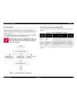
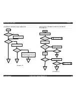
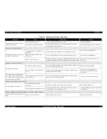
Troubleshooting
Overview
59
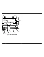
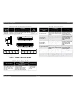
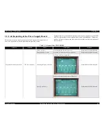
Figure
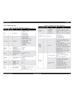
3-2. Printhead Connector Pin Alignment
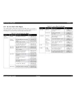
Table
3-2. Printhead Coil Resistance Test Points
Common
Pin
No.
Test
Pin No.
Test
Method
(Set
meter to ohms. Disconnect the
printhead
after the printer is powered off.)
Meter
Reading
Refer
to the
figure
below.
Refer
to the
figure
below.
Place
one lead on each pin and the other lead
on
each common pin.
29.6±3.0
Ω
(at
25°C, 77°F)
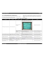
Table
3-3. Printhead Driver Test Pin
Transistor
Numbers
Test
Method
(Set
meter to diodes. Check with
printer
power off.)
Meter
Reading
Q2,
Q3, Q4, Q5, Q6,Q7, Q8,
Q9,
Q10,Q11,Q12, Q13,
Q14,
Q15, Q16, Q17, Q18,
Q19,
Q20
Check
the following:
-From
the base to the collector
-From
the base to the emitter
Reverse
the leads and test again.
The
tester shows
neither
open nor
shorted.
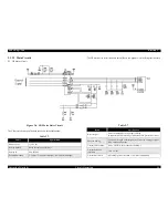
3
15 C5 2 C6 5 16 11 C7 17 C8
14 4
8
1
9
13 7 C1
18 C2 12 C3 C4
6 10 T
T
X
X
X
X
X
X
R
F
R
F
F
COM.
C1
C2
C3
C4
1.7.13
9
10.18
6.12
R
COM.
C5
C6
C7
C8
2.5.11
3.15
16.17
4.8.14
Pin No,
Pin No,
T : Thermistor terminal
X : Not used
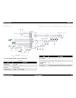
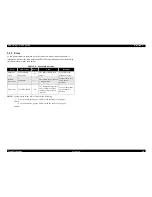
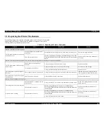
Table
3-4. Detector Test Point
Detector
Connector
Number
Test
Method
(Set
meter to ohms. Check with
printer
power off.)
Meter
Reading
HP
Detector (CN4)
Place
one lead on pin 1 and the other
lead
on pin 2, and toggle the detector
actuator.
Meter
should toggle between
open
and short. (LOW:
within
CR Home position.)
Front
PE (FPE)
Detector
(CN6)
Place
one lead on pin 1 and the other
lead
on pin 2, and toggle the detector
actuator.
Meter
should toggle between
open
and short. (HIGH:
paper
is installed in the
printer.)
Rear
PE (RPE)
Detector
(CN7)
Place
one lead on pin 1 and the other
lead
on pin 2, and toggle the detector
actuator.
Meter
should toggle between
open
and short. (HIGH:
paper
is installed in the
printer.)
Release
Lever Detector
(CN5)
Place
one lead on pin 1 and the other
lead
on pin 2, and toggle the detector
actuator.
Meter
should toggle between
open
and short. (HIGH:
Friction
Feed mode.)
PG
Detector (CN8)
Place
one lead on pin 1 and the other
lead
on pin 2, and move the detector
actuator
from -0 to 6.
Meter
should toggle between
open
and short. (HIGH: PG -
1
~ 3.)
Printhead
thermistor
Place
one lead on pin T and the other
lead
on other pin T to check the
resistance.(Refer
to Fig.3-2.)
Approx.
14K
Ω
(at 17°C)
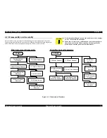
Summary of Contents for LQ-570e
Page 8: ...C H A P T E R 1 PRODUCT DESCRIPTION ...
Page 46: ...C H A P T E R 2 OPERATINGPRINCIPLES ...
Page 57: ...C H A P T E R 3 TROUBLESHOOTING ...
Page 70: ...C H A P T E R 4 DISASSEMBLYANDASSEMBLY ...
Page 93: ...C H A P T E R 5 ADJUSTMENT ...
Page 101: ...C H A P T E R 6 MAINTENANCE ...
Page 106: ...C H A P T E R 7 APPENDIX ...
Page 127: ......
Page 128: ......
Page 129: ......


