EPSON
LQ-570e/LQ-580
Revision
C
Adjustment
Adjustment
and Resetting the Printer
96
5.2.2
Platen Gap Adjustment
The
tools requred in the platen gap adjustment are;
o
Motor
Driver
o
Motor
Driver Bit (Hezagon)
o
Thickness
gauge (0.33 : 0.36)
If
the guide CR shaft or adjust parallel bushing is rotated or reassembled, or printing is too
faint
or stained, the Plate Gap adjustment must be performed in the following order:
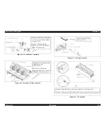
1.
Set
the adjust lever gap on 2nd position where is 2nd square hole from bottom on the
left
frame assembly.
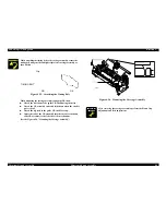
Figure
5-2. Position”0” (2nd Position)
2.
Set
Adjust Lever Holding Fixture on the left frame assembly.
3.
Insert
the Thickness Gauge stick into the hole of the guide CR shaft.
4.
Turn
the guide CR shaft using Platen Gap Adjustment stick to adjust platen gap (PG).
NOTE: Platen
Gap: 0.33
→
OK,
0.36
→
NG
NOTE: Judge
whether Thickness Gauge drops or not. If the Thickness Gauge
does
not drop, ajust the platen gap again.
NOTE: The
adjust gap lever must be fixed to the stopper of Adjust Lever Holding
Fixture.
5.
Permanently
secure the hexagon nut (normal, M4) to fix the adjust gap lever.
NOTE: Tightening
Torque is 14 to 16 kg/cm.
The
adjust gap lever and the guide CR shaft must be firmly held by fixture.
6.
Recheck
Platen Gap has been adjusted within specification, after securing the hexagon
nut
(normal, M4).
NOTE: Adjust
Gap Lever must be set on 2nd position.
NOTE: If
Platen Gap is out of specification, repeat process 4 to 6 until Platen
Gap
becomes within specification.
NOTE: Platen
Gap: 0.33
→
OK,
0.36
→
NG
7.
Remove
Platen Gap Adjustment stick and Adjust Lever Holding Fixture.
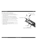
Figure
5-3. Platen Gap Adjustment
FRAME ASSY.,LEFT
LEVER,GAP,ADJUST
HEXAGON NUT,NORMAL,M4
2
nd
Groove
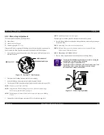
C H E C K
P O I N T
n
The
Adjust Parallel Bushing should not move when turning the
Adjust
Gap Lever from 1st step to 8th step.
n
The
Adjust Gap Lever should not bent.
n
The
Adjust Gap Lever should be able to stay in each steps. If no
click
feeling occurs, remove the hexagon nut and change
direction
of the Toothed Lock Washer.
PRINT HEAD
THICKNESS GAUGE
PLATEN
PLATEN GAP
Summary of Contents for LQ-570e
Page 8: ...C H A P T E R 1 PRODUCT DESCRIPTION ...
Page 46: ...C H A P T E R 2 OPERATINGPRINCIPLES ...
Page 57: ...C H A P T E R 3 TROUBLESHOOTING ...
Page 70: ...C H A P T E R 4 DISASSEMBLYANDASSEMBLY ...
Page 93: ...C H A P T E R 5 ADJUSTMENT ...
Page 101: ...C H A P T E R 6 MAINTENANCE ...
Page 106: ...C H A P T E R 7 APPENDIX ...
Page 127: ......
Page 128: ......
Page 129: ......

