EPSON
LQ-570e/LQ-580
Revision
C
7
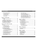
2.3.2
Input
and
Output
Specification
..................................................
50
2.3.3
C293MAIN
Board
Circuit
...........................................................
52
2.3.3.1
Main
Components
..............................................................
53
2.3.3.2
Main
Circuits
.......................................................................
54
2.3.4
C293
PNL
Board
Circuit
............................................................
56
2.3.4.1
Switch
Port
.........................................................................
56
2.3.4.2
LED
Port
.............................................................................
56
Chapter
3 Troubleshooting
3.1
Overview
...........................................................................................
58
3.1.1
Main
Component
Checking
Point
..............................................
58
3.1.2
Error
..........................................................................................
60
3.2
UNIT
LEVEL
TROUBLESHOOTING
................................................
61
3.3
Unit
Repairing
of
the
Power
Supply
Board
...................................
65
3.4
Unit
Repairing
of
the
MAIN
Board
..................................................
67
3.5
Repairing
the
Printer
Mechanism
..................................................
68
Chapter
4 Disassembly and Assembly
4.1
Overview
...........................................................................................
71
4.1.1
Disassembly
Precautions
..........................................................
71
4.1.2
Tools
and
Instruments
...............................................................
71
4.1.3
Service
Check
After
Repair
.......................................................
72
4.1.4
Specifications
for
Screws
..........................................................
73
4.2
Disassembly
and
Assembly
...........................................................
74
4.2.1
Pre-disassembly
Procedures
....................................................
75
4.2.1.1
Front
Cover
Assembly
Removal
.........................................
75
4.2.1.2
EJ
(Paper
Eject)
Assembly
Removal
..................................
76
4.2.1.3
Tractor
Assembly
Removal
................................................
76
4.2.2
Printhead
Removal
....................................................................
77
4.2.3
HP
(Home
Position)
Detector
Removal
.....................................
78
4.2.4
Upper
Housing
Assembly
Removal
...........................................
79
4.2.5
C293
MAIN
Board
Removal
......................................................
80
4.2.6
C293
PSB/PSE
Board
Removal
................................................
82
4.2.7
Printer
Mechanism
Removal
.....................................................
83
4.2.8
Platen
Removal
.........................................................................
84
4.2.9
Printer
Mechanism
Disassembly
...............................................
85
4.2.9.1
CR
Motor
Removal
.............................................................
85
4.2.9.2
PF
Motor
Removal
.............................................................
85
4.2.9.3
PF
Gear
Train
Disassembly
...............................................
86
4.2.9.4
PG
(Platen
Gap)
Detector
Removal
...................................
87
4.2.9.5
Release
Detector
Removal
................................................
87
4.2.9.6
Front
PE
(Paper
End)
Detector
Removal
...........................
88
4.2.9.7
Front
PE
(Paper
End)
Detector
Removal
...........................
88
4.2.9.8
Carriage
Assembly
Removal
..............................................
89
4.2.9.9
Rear
Paper
Guide
Assembly
Removal
...............................
91
4.2.9.10
Ribbon
Drive
(RD)
Assembly
Removal
............................
92
Chapter
5 Adjustment
5.1
Adjustment
Overview
......................................................................
94
5.1.1
Required
Adjustment
.................................................................
94
5.1.2
Adjustment
Tools
......................................................................
94
5.2
Adjustment
and
Resetting
the
Printer
...........................................
95
5.2.1
Parallel
Adjustment
...................................................................
95
5.2.2
Platen
Gap
Adjustment
.............................................................
96
5.2.3
Factory
Setting
..........................................................................
97
5.2.4
Bi-D
Adjustment
........................................................................
99
5.2.4.1
Bi-d
Specifications
..............................................................
99
5.2.4.2
Bi-d
Adjustment
Method
.....................................................
99
Chapter
6 Maintenance
6.1
Preventive
Maintenance
...............................................................
102
6.2
Lubrication
.....................................................................................
103
Chapter
7 Appendix
7.1
Connector
summary
.....................................................................
107
7.2
EEPROM
Address
Map
.................................................................
112
7.3
Components
Layout
......................................................................
118
7.4
Exploded
Diagram
.........................................................................
121
7.5
Parts
List
........................................................................................
123
7.6
Circuit
Diagrams
............................................................................
126
Summary of Contents for LQ-570e
Page 8: ...C H A P T E R 1 PRODUCT DESCRIPTION ...
Page 46: ...C H A P T E R 2 OPERATINGPRINCIPLES ...
Page 57: ...C H A P T E R 3 TROUBLESHOOTING ...
Page 70: ...C H A P T E R 4 DISASSEMBLYANDASSEMBLY ...
Page 93: ...C H A P T E R 5 ADJUSTMENT ...
Page 101: ...C H A P T E R 6 MAINTENANCE ...
Page 106: ...C H A P T E R 7 APPENDIX ...
Page 127: ......
Page 128: ......
Page 129: ......

