


EPSON
LQ-570e/LQ-580
Revision
C
Disassembly
and Assembly
Disassembly
and Assembly
88
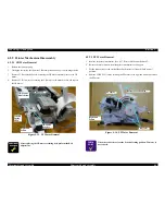
4.2.9.8
Carriage Assembly Removal
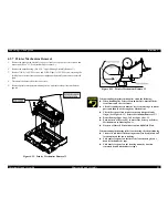
1.
Remove
the printer mechanism. (See 4.2.7 "Printer Mechanism Removal".)
2.
Remove
the upper head cable and the lower head cable from the printhead. (See 4.2.1
"Pre-disassembly
Procedures".)
3.
Remove
the platen cover and remove platen. (See 4.2.8 "Platen Removal".)
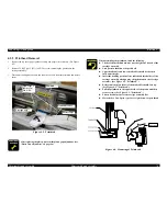
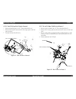
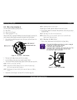
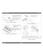
4.
Remove
the hexagon nut, release lever, washer and the bushing parallel adjust. (See
the
figure below.)
Figure
4-23. Carriage Assembly Removal 1
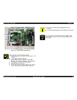
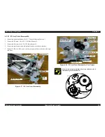
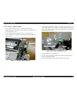
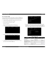
5.
Rotate
the adjust parallel bushing until the tab (in the figure, the tab is not visible, for it
is
on the back side from this view) enabled to come out of the cutout section of the rear
frame.
(See the figure below.) Remove the adjust parallel bushing. Use the parallelism
adjustment
spanner if necessary.
Figure
4-24. Carriage Assembly Removal 2
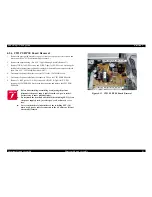
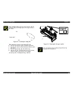
6.
Disengage
the timing belt from the CR motor.
7.
Move
the carriage assembly to the far right end, and remove it from the rack of the
front
frame with the guide CR shaft.
8.
Release
the timing belt from 2 clips at the bottom of the carriage assembly.
Release
Lever
Hexagon Nut
Bushing Parallel Adjust
Washer
Guide
CR Shaft
Rear
Frame
1
2
Bushing Parallel Adjust
Washer
Guide
CR Shaft
Summary of Contents for LQ-570e
Page 8: ...C H A P T E R 1 PRODUCT DESCRIPTION ...
Page 46: ...C H A P T E R 2 OPERATINGPRINCIPLES ...
Page 57: ...C H A P T E R 3 TROUBLESHOOTING ...
Page 70: ...C H A P T E R 4 DISASSEMBLYANDASSEMBLY ...
Page 93: ...C H A P T E R 5 ADJUSTMENT ...
Page 101: ...C H A P T E R 6 MAINTENANCE ...
Page 106: ...C H A P T E R 7 APPENDIX ...
Page 127: ......
Page 128: ......
Page 129: ......