EPSON
LQ-570e/LQ-580
Revision
C
Disassembly
and Assembly
Disassembly
and Assembly
74
4.2.1
Pre-disassembly Procedures
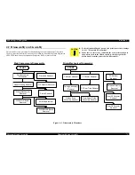
Before
starting disassembly procedures, the following parts must be removed. (see the
figure
below.)
Figure
4-2. Parts Name
Remove
the top cover and paper guide assembly. Removal of the other parts is explained in
detail
below.
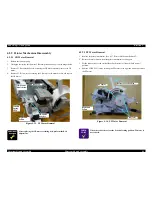
4.2.1.1
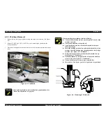
Front Cover Assembly Removal
FRONT
COVER ASSEMBLY
1.
Open
the front cover assembly by releasing 2 top hooks locking the upper housing.
2.
Release
2 hooks on bottom side of the front cover assembly from the location shafts of
lower
housing from the front bottom.
NOTE: 2
hooks and 2 location shafts must be free from any damage, -crack, bent
nor
white mark.
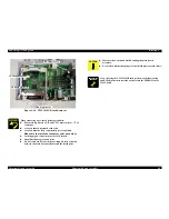
KNOB
1.
Pull
out the knob from the shaft of the platen.
Paper
Guide Assembly
Top
Cover
Front
Cover
Tranctor
Assembly
Knob
To
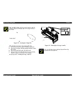
push the front cover assembly, do not push vertically or
horizontally.
Must push about 45 degree from front.
Matching
the “D”-shaped cut.
Summary of Contents for LQ-570e
Page 8: ...C H A P T E R 1 PRODUCT DESCRIPTION ...
Page 46: ...C H A P T E R 2 OPERATINGPRINCIPLES ...
Page 57: ...C H A P T E R 3 TROUBLESHOOTING ...
Page 70: ...C H A P T E R 4 DISASSEMBLYANDASSEMBLY ...
Page 93: ...C H A P T E R 5 ADJUSTMENT ...
Page 101: ...C H A P T E R 6 MAINTENANCE ...
Page 106: ...C H A P T E R 7 APPENDIX ...
Page 127: ......
Page 128: ......
Page 129: ......


