


EPSON
LQ-570e/LQ-580
Revision
C
Disassembly
and Assembly
Disassembly
and Assembly
84
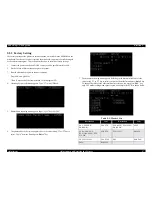
4.2.9
Printer Mechanism Disassembly
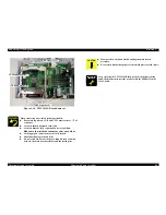
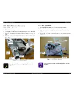
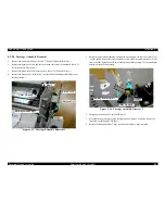
4.2.9.1
CR Motor Removal
1.
Release
the tension spring.
2.
Disengage
the timing belt from the CR motor pinion and hang it on the hanger below.
3.
Remove
2 CR mount shaft screws securing the CR motor assembly remove the CR
motor.
4.
Remove
2 CB (3x6) screws securing the CR motor to the motor bracket, and remove
the
CR motor.
Figure
4-15. PF Motor Removal
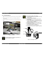
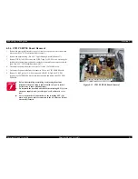
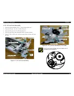
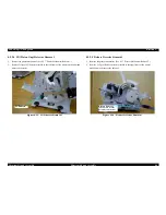
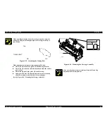
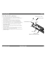
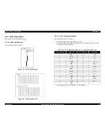
4.2.9.2
PF Motor Removal
1.
Remove
the printer mechanism. (See 4.2.7 "Printer Mechanism Removal")
2.
Release
the motor harness from the printer mechanism securing part.
3.
Set
the release lever to the vertical (Rear Push tractor) or forward (Push tractor)
position.
4.
Remove
2 CBS (3x8) screws securing the PF motor to the right sub frame and remove
the
PF motor.
Figure
4-16. PF Motor Removal
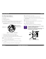
A D J U S T M E N T
R E Q U I R E D
After
replacing the CR motor or timing belt, perform the Bi-d
adjustment.
Tension
Spring,
1056
Right
Sub
Frame
CR
Motor
Bracket
CR
Motor
CR
Mount
Shaft
Screw
C H E C K
P O I N T
When
the release lever is at the Friction feeding position, PF motor is
not
released.
Release
Lever Position
PF
Motor
CBS
(3x8)
Right
Sub
Frame
Summary of Contents for LQ-570e
Page 8: ...C H A P T E R 1 PRODUCT DESCRIPTION ...
Page 46: ...C H A P T E R 2 OPERATINGPRINCIPLES ...
Page 57: ...C H A P T E R 3 TROUBLESHOOTING ...
Page 70: ...C H A P T E R 4 DISASSEMBLYANDASSEMBLY ...
Page 93: ...C H A P T E R 5 ADJUSTMENT ...
Page 101: ...C H A P T E R 6 MAINTENANCE ...
Page 106: ...C H A P T E R 7 APPENDIX ...
Page 127: ......
Page 128: ......
Page 129: ......