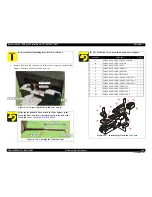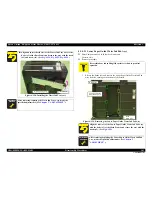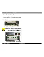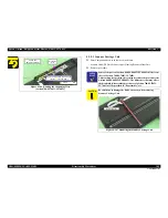
Epson Artisan 700/Epson Stylus Photo PX700W/TX700W
Revision C
DISASSEMBLY/ASSEMBLY
Disassembly Procedures
157
Confidential
17.
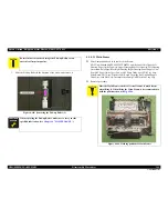
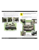
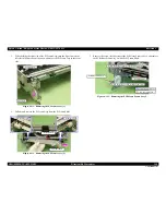
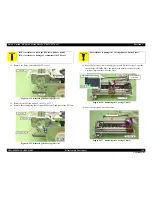
Slide the Carriage Shaft to the 80 digit side, and detach the point B of the
Carriage Shaft from the Main Frame, and remove the Carriage Unit together
with the CR Timing Belt and the Carriage Shaft.
Figure 4-138. Removing the Carriage Unit (7)
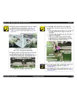
Align the point A on the rear of the Carriage Unit with the
cutout of the CR Guide Plate to install the Carriage Unit. (See
Fig. 4-136
.)
When installing the Flat Washer and the Spring Washer, install
them in the order of the Flat Washer and the Spring Washer
from the frame side. (See
Fig. 4-133
.)
When installing the Torsion Spring R, hook the spring leg
between PG Cam R and the Spring Washer, and attach the
spring to the ribs (x2) of the Main Frame. (See
Fig. 4-132
,
Fig.
4-133
.)
When installing the Torsion Spring L, hook the spring leg
between PG Cam L and the Main Frame, and attach it to the
ribs (x2) of the Main Frame. (See
Fig. 4-135
.)
When installing the Frame Sheet, attach it with double-sided
tape while aligning it with the edge of the Main Frame. (See
Fig. 4-132
.)
Carriage Unit
Carriage Shaft
Point B
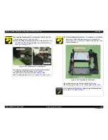
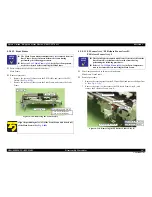
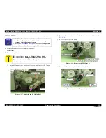
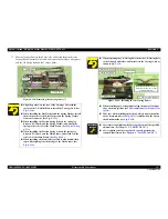
When replacing the CR Timing Belt, insert the CR Timing Belt
to the Timing Belt Holder, and install it to the Carriage Unit as
shown in
Fig. 4-139
.
Figure 4-139. Installing the CR Timing Belt (1)
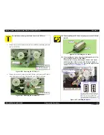
When installing the Carriage Shaft, align the phase of the Spur
Gear on the 0 digit side. (See
Phase adjustment of the Spur Gear
(p154)
.)
Take care when installing the Driven Pulley, because the pulley
on the 0-column side (see
Fig. 4-131
) is smaller than the one on
the 80-column side (see
Fig. 4-129
).
A D J U S T M E N T
R E Q U I R E D
After removing/replacing the Carriage Unit, make the specified
adjustments. (See
Chapter 5 "ADJUSTMENT"
.)
After replacing the Carriage Unit, be sure to perform the
required lubrication. (See
Chapter 6 "MAINTENANCE"
.)
C.B.P. 3x8 (6±1Kgfcm)
Timing Belt Holder
Carriage Unit
CR Timing Belt
Insert the area that has teeth on
both sides to the groove of the
Timing Belt Holder
Rear side of the Carriage Unit
Summary of Contents for Artisan 700 Series
Page 7: ...Confidential C H A P T E R 1 PRODUCTDESCRIPTION ...
Page 42: ...Confidential C H A P T E R 2 OPERATINGPRINCIPLES ...
Page 48: ...Confidential C H A P T E R 3 TROUBLESHOOTING ...
Page 189: ...Confidential C H A P T E R 5 ADJUSTMENT ...


