Epson Artisan 700/Epson Stylus Photo PX700W/TX700W
Revision C
DISASSEMBLY/ASSEMBLY
Disassembly Procedures
145
Confidential
1.
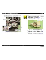
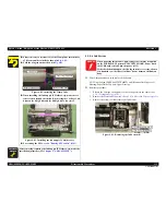
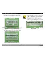
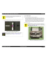
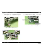
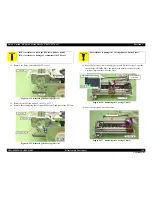
Release the Plunger cable from the hooks (x10) of the Front Frame. (See
Fig.
4-105
.)
2.
Release the PE Sensor cable from the dowel of the Base Frame. (See
Fig.
4-105
.)
3.
Detach the relay connector of the PE Motor cable from the hole of the Base
Frame, and disconnect the connector. (See
Fig. 4-105
.)
Figure 4-105. Removing the Main Frame (1)
4.
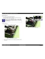
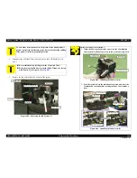
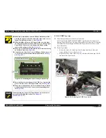
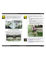
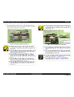
Remove the Grounding Plate B. (See
Fig. 4-106
.)
5.
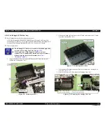
Remove the screws (x7) that secure the Main Frame, and remove the Main
Frame from the Base Frame.
Figure 4-106. Removing the Main Frame (2)
Dowel of the Base Frame
PE Sensor Cable
Front Frame
Plunger Cable
Hook
Connector of the PF
Motor Cable
Hole of the Base Frame
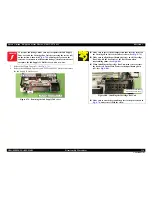
C A U T I O N
When removing the Main Frame, be careful not to damage the
cables and FFCs with the Main Frame.
5
Grounding
Plate A
(Under the
Frame)
Grounding
Plate B
4
6
7
1
2
3
C.B.P. 3x8 (6±1Kgfcm)
Positioning
hole & dowel
Summary of Contents for Artisan 700 Series
Page 7: ...Confidential C H A P T E R 1 PRODUCTDESCRIPTION ...
Page 42: ...Confidential C H A P T E R 2 OPERATINGPRINCIPLES ...
Page 48: ...Confidential C H A P T E R 3 TROUBLESHOOTING ...
Page 189: ...Confidential C H A P T E R 5 ADJUSTMENT ...

