background image

Repeater Statistics

5-7

Managing Ethernet MicroLAN Modules

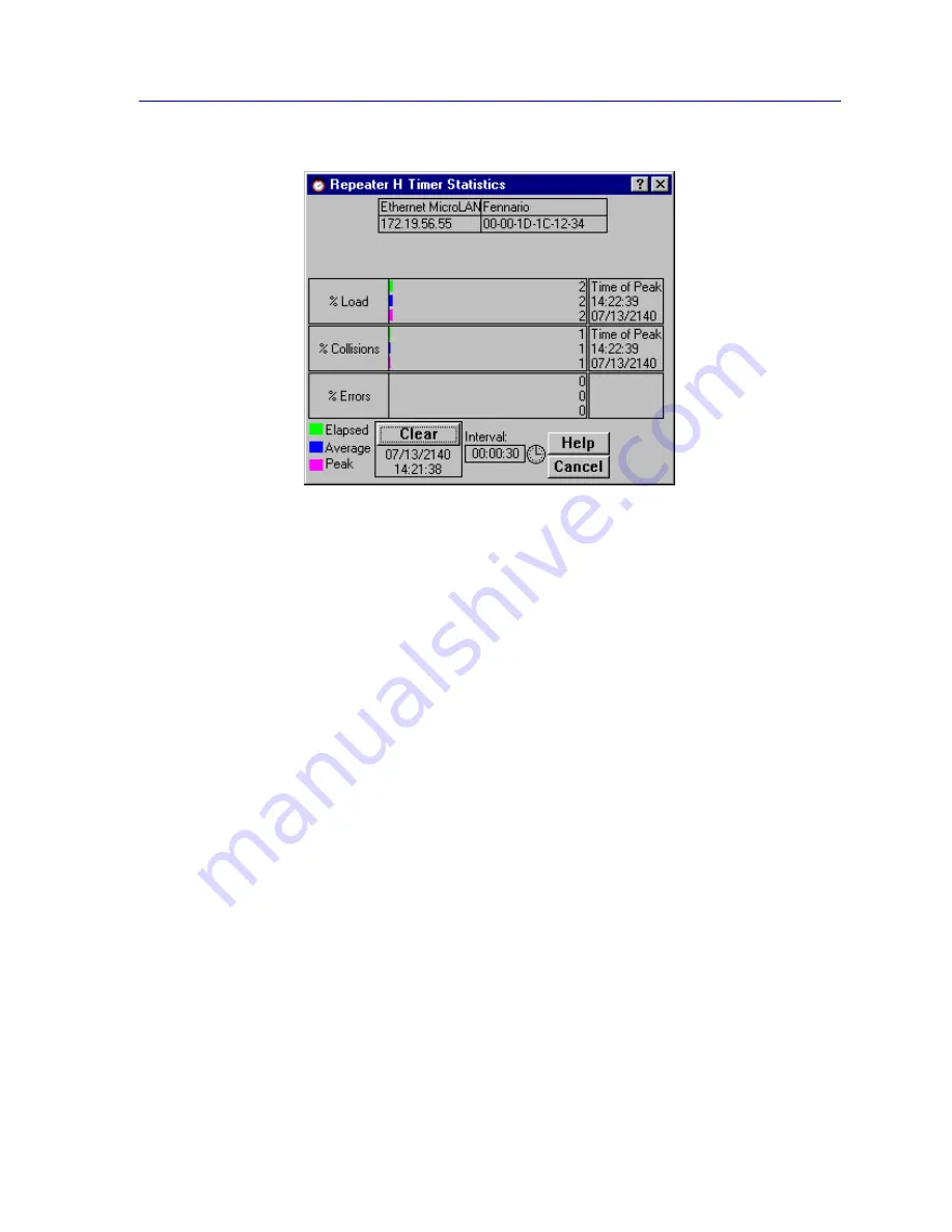
Figure 5-2. The Repeater Timer Statistics Window

To open the board-level Timer Statistics window:

1.

Click on the appropriate Module Index to display the Module menu.

2.

Drag down to select the appropriate repeater channel (A - H), then right to 
reveal the board-level Repeater menu.

3.

Select Timer Statistics. The board-level Timer Statistics window will appear.

To access the port-level Timer Statistics window:

1.

Click on the appropriate Port to display the port menu.

2.

Select Timer Statistics. The port-level Timer Statistics window will appear.

The Board and Port Timer Statistics windows are similar to the Repeater Timer Statistics 
window displayed in 

Figure 5-2

, except that they display statistics applicable to the board 

or the port. 

The Timer Statistics windows display the elapsed, average, and peak values for the 
following statistics:

% Load

The percentage of total theoretical load processed by the selected repeater, board, or port 
during the user-defined time interval. For standard Ethernet, the total theoretical load is 10 
Mbps.

% Collisions

The percentage of collisions processed by the selected repeater, board, or port during the 
user-defined time interval.

Summary of Contents for SmartSwitch 6000

Page 1: ...SmartSwitch 6000 and Matrix E7 Modules User s Guide ...

Page 2: ......

Page 3: ...hat the Licensed Software is virus free Copyright 2000 2001 by Enterasys Inc All rights reserved Printed in the United States of America Order Number 9033404 02 Enterasys Inc P O Box 5005 Rochester NH 03866 5005 Enterasys NetSight and Matrix E7 are trademarks of Enterasys MiniMMAC FNB Multi Media Access Center and DNI are registered trademarks and Portable Management Application IRM IRM2 IRM3 IRBM...

Page 4: ...erative 3 Reproduced for safekeeping archives or backup purposes 4 Modified adapted or combined with other computer software provided that the modified combined or adapted portions of the derivative software incorporating restricted computer software are made subject to the same restricted rights 5 Disclosed to and reproduced for use by support service contractors in accordance with subparagraphs ...

Page 5: ...iii ...

Page 6: ...iew 2 14 Port Status Color Codes 2 19 The Chassis Backplane View 2 20 The Chassis Backplane View 2 20 The Chassis Manager Window 2 23 The Module Information Window 2 24 Viewing Hardware Types 2 25 Device Type 2 26 Module Type 2 26 Interface Description 2 26 Viewing I F Summary Information 2 27 Interface Performance Statistics 2 28 Viewing Interface Detail 2 30 Using the Device Find Source Address ...

Page 7: ... Performing Ingress List Configuration 2 75 Performing Egress List Configuration 2 78 VLAN and Priority Configuration 2 81 Configuring Bridge and Bridge Port Capability 2 81 Setting VLAN Parameters and Operational Modes 2 84 Configuring Basic VLAN Port Parameters 2 87 Configuring Advanced VLAN Port Parameters 2 89 Performing Egress List Configuration 2 93 Setting Port Priority 2 96 Setting Port Pr...

Page 8: ...cs 5 1 The Statistics Windows 5 2 Accessing the Statistics Windows 5 2 Statistics Defined 5 3 Using the Total and Delta Option Buttons 5 5 Timer Statistics 5 6 Accessing the Timer Statistics Windows 5 6 Setting the Timer Statistics Interval 5 8 Repeater Performance Graphs 5 8 Accessing the Performance Graph Windows 5 9 Configuring the Performance Graphs 5 12 The Detail Button 5 12 Using Port Locki...

Page 9: ...I Frame Translation Settings 6 14 Information about Ethernet and FDDI Frame Types 6 15 Ethernet Frames 6 16 FDDI Frames 6 17 FDDI Frame Translation Options 6 18 Chapter 7 ATM Configuration Accessing the ATM Connections Window 7 1 Configuring Connections 7 4 Adding a New Connection 7 4 Deleting a Connection 7 4 Chapter 8 HSIM W87 Configuration The T3 Configuration Window 8 1 The T1 Configuration Wi...

Page 10: ...has a removable fan tray installed underneath the module slots it also has two slots for dual redundant power supplies installed across the bottom of the chassis The SmartSwitch 6000 Frame Transfer Matrix FTM backplane and Matrix E7 nTERA backplane provide distributed processing power The backplane s passive design provides a separate independent backplane connection from each module in the chassi...

Page 11: ...has full duplex capability allowing for a 200 Mbps connection to another HSIM F6 The HSIM A6DP is an Asynchronous Transfer Mode ATM HSIM which provides an ATM uplink via two media configurable ATM Port Interface Modules APIMs The dual APIM design allows for a redundant connection to the uplink so that if the primary interface fails the secondary interface will automatically take over The HSIM A6DP...

Page 12: ...r s Guide for more information Once it has been added to your List Tree or Map view you can access and manage the HSIM according to the information in Chapter 2 The Device View The 6E128 26 and 6E129 26 SmartSwitch modules each provide 24 fixed Ethernet fiber ports multi mode fiber on the 6E128 single mode fiber on the 6E129 via ST connectors plus two slots for FEPIMs The 6E138 25 and 6E139 25 Sma...

Page 13: ... Ethernet connectivity the GPIM 09 which offers one SC connector for MMF or SMF 1000Base LX connectivity or the GPIM 04 which offers one ANSI Fibrechannel style 2 connector for 150 Ohm STP 1000Base CX connectivity The 6H203 24 and 6H253 13 SmartSwitch modules are 10 100 Fast Ethernet modules The 6H203 24 provides 24 ports via dual RJ21 connectors The 6H253 13 provides 12 10 100 Fast Ethernet ports...

Page 14: ...plane bandwidth capacity of up to 3 2 Gbps Support for redundant load sharing power supplies to provide fault tolerance Enterasys LANVIEW Diagnostic LEDs for quick visual diagnosis of interface and device performance a single removable fan tray a 19 footprint for ease of installation in rack mounts and front panel accessibility to all chassis components for easy maintenance Using the SmartSwitch 6...

Page 15: ...front panel COM port and any attached Uninterruptable Power Supply UPS Chapter 3 Statistics describes the two statistics views available at the interface level MIB II Interface statistics and RMON Ethernet statistics Chapter 4 Alarm Configuration provides instructions for using both the Basic and Advanced alarm applications to configure both alarms and the events that notify you that an alarm cond...

Page 16: ...rtSwitch 6000 and Matrix E7 consult the appropriate hardware documentation Getting Help This section describes different methods of getting help for questions or concerns you may have while using NetSight Element Manager Using On line Help You can use the Help buttons to obtain information specific to a particular window When you click on a Help button a window will appear which contains context s...

Page 17: ...W GRFXPHQWDWLRQ WR 1HW6LJKW 7HFKQLFDO RPPXQLFDWLRQV YLD WKH IROORZLQJ H PDLO DGGUHVV 1HWVLJKWBGRFV HQWHUDV V FRP Getting Technical Support Online Services on the World Wide Web 7R ORFDWH SURGXFW VSHFLILF LQIRUPDWLRQ UHIHU WR WKH QWHUDV V HE3DJH DW WKH IROORZLQJ DGGUHVV KWWS ZZZ HQWHUDV V FRP Global Technical Assistance Center I RX KDYH DGGLWLRQDO TXHVWLRQV FRQWDFW WKH ORDEO 7HFKQLFDO VVLVWDQFH HQW...

Page 18: ...roduction 7HOHSKRQH KRXUV D GD GD V D HDU D OHFWURQLF 0DLO VXSSRUW HQWHUDV V FRP 0DLOLQJ GGUHVV QWHUDV V 1HWZRUNV QF 7HFKQLFDO 6XSSRUW QGXVWULDO D 5RFKHVWHU 1 73 IWS FDEOHWURQ FRP RJLQ DQRQ PRXV 3DVVZRUG RXU HPDLO DGGUHVV ...

Page 19: ...Introduction 1 10 Getting Help ...

Page 20: ...manage The Management Selection window Figure 2 1 will appear or 1 In any map list or tree view click the left mouse button once to select the device you wish to manage 2 Select Manage Node from the primary window menu bar or select the Manage Node toolbar button The Management Selection window Figure 2 1 will appear or 1 In any map list or tree view click the right mouse button once to select the...

Page 21: ...urrent configuration and status of all the port interfaces on the module Note that the module will appear in its corresponding physical slot in the SmartSwitch 6000 or Matrix E7 Slots are numbered from 1 5 for the SmartSwitch 6000 or 1 7 for the Matrix E7 from left to right in the chassis The Device View also will provide you with environmental status information about the fan tray and power suppl...

Page 22: ...ows TIP When you move the mouse cursor over a management hot spot the cursor icon will change into a hand symbol to indicate that clicking in the current location will bring up a management option NOTE Note that up to 22 ports can be displayed simultaneously on a module If a module has a higher port density than 22 ports arrows will appear at the top and bottom of the port stack so that you can sc...

Page 23: ...lid connection Magenta indicates that the SmartSwitch 6000 or Matrix E7 module is in a temporary stand by mode while it responds to a physical change in the hub such as when a module is inserted Note that module and port menus are inactive during this stand by state Blue indicates an unknown contact status polling has not yet been established with the SmartSwitch 6000 or Matrix E7 module Red indic...

Page 24: ... Time The current time in a 24 hour hh mm ss format set in the SmartSwitch 6000 or Matrix E7 module s internal clock Date The current date in an mm dd yyyy format set in the SmartSwitch 6000 or Matrix E7 module s internal clock 6C105 6C107 Chassis specific Information The Device View provides the following information about the 6C105 or 6C107 chassis in which the SmartSwitch 6000 or Matrix E7 modu...

Page 25: ...eturned are Not Available Yellow No response has been returned from the device regarding the power supplies Normal Green A power supply is installed and operating in the associated power slot Fault Red The power supply in the associated power slot is not operational Not Installed Blue The indicated power slot is not occupied by a power supply Fan Tray Status The 6C105 6C107 supports a single remov...

Page 26: ...you have installed the module can also be configured to perform pre standard 802 1Q VLAN switching or Enterasys SecureFast Switching Check your firmware release notes to see if your version of firmware supports these features For SmartSwitch 6000 and Matrix E7 modules that support 802 1Q VLANs or SecureFast Switching the toggle from traditional bridging to 802 1Q or SecureFast Switching is perform...

Page 27: ...6DP module installed The VLAN option will appear if your device has been configured to operate in 802 1Q mode The Priority Configuration option will appear if your device supports 802 1P Dynamic Multicast Filtering Priority Queuing The UPS option will only appear if your COM port has been configured for use with an Uninterruptable Power Supply No bridge related options appear in any menus if the d...

Page 28: ...evice See Viewing I F Summary Information on page 2 27 for details 802 1Q VLAN appears in the Device menu if your module is configured to operate in 802 1Q mode The windows launched via the VLAN option allow you to configure and operate port based VLANs on the module See 802 1Q VLANs on page 2 70 for details ATM Connections appears in the Device menu if you have an HSIM A6DP installed in your modu...

Page 29: ...enu lets you switch the front panel display between three graphical representations of the device The Logical view provides the logical front panel display of the SmartSwitch 6000 or Matrix E7 module and its interfaces The BackPlane Config view displays the backplane connections between the SmartSwitch 6000 or Matrix E7 module and other modules installed in the 6C105 6C107 chassis Refresh updates ...

Page 30: ...ernet MicroLAN modules the Port Status menu will contain the following options Load will display the portion of network load processed by each port as a percentage of the theoretical maximum load of the connected network segment 10 100 155 5 800 or 1000 Mbps Port Assignment will display each port s repeater channel assignment A H Status allows you to select one of three status type displays Admin ...

Page 31: ...ion These selections are also available from the Tools menu at the top of the primary NetSight Element Manager window The Help Menu The Help Menu has the following three selections MIBs Supported brings up the Chassis Manager window described later in this chapter Chassis Manager Help brings up a help window with information specifically related to using the Chassis Manager and Device View windows...

Page 32: ...he method that bridges use to decide the controlling root bridge when two or more bridges are in parallel Refer to the Bridging chapter in the Element Manager Tools Guide for more information SmartTrunk invokes the SmartTrunk Configuration and Status Screen which enables you to group interfaces logically to achieve greater bandwidth between devices if both devices support the SmartTrunk feature Th...

Page 33: ...lable for the selected port For standard Ethernet and Fast Ethernet ports RMON statistics will be displayed if the RMON Default MIB component is active if it has been disabled MIB II interface statistics will display See Chapter 3 Statistics for more information Enable Disable Port which activates or disables bridging for the selected port respectively refer to the Bridging chapter in the Element ...

Page 34: ...base is being created or the Spanning Tree Algorithm is being executed because of a network topology change The port is monitoring network traffic and learning network addresses BLK Blocking if the port is on line but filtering traffic from going across the SmartSwitch 6000 or Matrix E7 from one network segment to another Bridge topology information will be forwarded by the port In the 5 1 x firmw...

Page 35: ... percentage reflects the number of errors generated during the last polling interval by devices connected to that port compared to the total number of valid packets processed by the port I F Mapping If you choose the I F Mapping mode the interface boxes will display the interface number ifIndex associated with each port on the SmartSwitch 6000 or Matrix E7 module I F Speed If you choose the I F Sp...

Page 36: ...inked Admin ON or OFF Link LNK link NLK not linked or N A not available If you have selected the Admin Link status mode a port is considered ON if the port is enabled and has a valid link OFF if it has not been enabled or if it has been disabled through management action SEG segmented if the port has been enabled by management and has a valid connection but has been segmented by the repeater becau...

Page 37: ...der Admin Link status mode BNC ports will display as ON if there is a valid connection and the port has been enabled OFF if the port has been disabled and SEG if the port has experienced 33 consecutive collisions or if there is no cable attached An AUI port will display as ON if the port has been enabled regardless of whether or not there is a valid connection OFF if the port has been disabled and...

Page 38: ...olor Codes Three of the Port Status display options Bridge Admin and Operator incorporate their own color coding schemes for the Bridge option green FWD blue DIS magenta LIS or LRN orange BLK and red BRK for Admin and Operator green ON red OFF and blue N A not available For all other Port Status selections Bridge Mapping Load Errors I F Mapping I F Speed and I F Type color codes will continue to r...

Page 39: ...he 6C105 or seven for the 6C107 point to point backplane connections between the monitored SmartSwitch 6000 or Matrix E7 module and other modules in the chassis The Backplane View also lets you disable those backplane connections The Chassis Backplane View The Chassis Backplane View Figure 2 4 indicates the operational status of the five point to point backplane connections between the monitored S...

Page 40: ...ment options for the individual interfaces To change the display form between Bridge and Interface click on the label and select the desired display form from the resulting menu Bridge is the default display form When the display form is in Bridge mode clicking on an interface results in a menu of options applicable to the selected backplane interface The Performance Graph option appears only if t...

Page 41: ...hile preparing to move to the forwarding state LRN Magenta The Forwarding database is being created or the Spanning Tree Algorithm is being executed because of a network topology change The interface is monitoring network traffic and learning network addresses BLK Orange The interface is on line but filtering traffic from going across the SmartSwitch 6000 or Matrix E7 from one module to another Br...

Page 42: ...Cabletron and Enterasys devices draw their functionality from a collection of proprietary MIBs and IETF RFCs In addition certain Enterasys intelligent devices like the SmartSwitch 6000 or Matrix E7 module organize their MIB data into a series of components A MIB component is a logical grouping of MIB data and each group controls a defined set of objects For example SmartSwitch 6000 or Matrix E7 mo...

Page 43: ...signed maintains the manufacturing data for the module and stores certain information such as the MAC addresses of various components Note that some devices will not return all the data displayed in the Module Information window these fields will remain blank To view the Module Information window 1 Click on the desired Module Index The Module menu will appear NOTE The Chassis Manager window will a...

Page 44: ... to be downloaded over the network Top Level Serial Number The top level serial number of the module associated with this PIC chip which provides encoded manufacturing date location serial number and top level revision number which can be used for troubleshooting information Base MAC Address The base MAC address in Ethernet format assigned to the module SMB 1 Prom Version This field is not applica...

Page 45: ... View window you can view a description of the Module types installed in your chassis To view a Module type 1 Click on the desired Module Index The Module menu will appear 2 Click on Module Type A Module Type text box similar to the example shown in Figure 2 8 will appear describing the module type Figure 2 8 Sample Module Type Text Box Interface Description Choosing the Description option from th...

Page 46: ...for the traffic processed by each network interface on your device The window also provides access to a detailed statistics window that breaks down Transmit and Receive traffic for each interface To access the I F Summary window 1 From the Device View click on the Device option from the menu bar 2 Click again to select I F Summary The I F Summary window Figure 2 10 will appear Figure 2 10 The I F ...

Page 47: ... Host Data Port for the on board i960 Host interface and ATM Enterasys ATM FDDI or Enterasys FDDI for an installed HSIM Physical Status Displays the current physical status or operational state of the interface Online or Offline Logical Status Displays the current logical status or administrative state of the interface Up or Down Interface Performance Statistics The statistical values and where av...

Page 48: ...interface including framing characters Out Packets Packets transmitted at the request of a higher level protocol by the device interface to a subnetwork address both unicast and non unicast Out Discards Outbound packets that were discarded by the device interface even though no errors were detected that would prevent them from being transmitted A possible reason for discard would be to free up buf...

Page 49: ...nterface statistical information including counts for both transmit and receive packets and error and buffering information for each individual port interface Color coded pie charts also let you graphically view statistics for both received and transmitted Unicast Multicast Discarded and Error packets To open the Interface Statistics window 1 In the I F Summary window click to select the interface...

Page 50: ...ress that is recognized by more than one device on the network segment The multicast field includes a count of broadcast packets those that are recognized by all devices on a segment These statistics are displayed in the pie chart color coded dark blue Discarded Displays the number of packets which were discarded even though they contained no errors that would prevent transmission Good packets are...

Page 51: ...ckets transmitted by this interface Making Sense of Detail Statistics The statistics available in this window can give you an idea of how an interface is performing by using the statistics in a few simple calculations it s also possible to get a sense of an interface s activity level To calculate the percentage of input errors Received Errors Packets Received To calculate the percentage of output ...

Page 52: ...iew menu bar 2 Click on Device Find Source Address The Device Find Source Address window as shown in Figure 2 12 will appear Figure 2 12 Device Find Source Address Window The Device Find Source Address window displays the following information Component Displays the type of interface through which the specified MAC address is communicating This field will report Bridge Port Instance Displays the b...

Page 53: ...g the 6E123 50 or 6E133 49 a search is made of both the Source Address Table SAT and the 802 1d Filtering database to discover through which interface s a specified source MAC address is communicating If the MAC address is found the interface types Bridge and Enet will display in the Component field with their associated port index number displayed in the Port Instance field To open the Device Fin...

Page 54: ... port index number associated with the interface on which the specified MAC address was found For an address found on a bridging interface this field displays the bridge interface index number on which the specified MAC address was found For an address found on a repeater port this field displays the board port group number and the port index number on which the specified MAC address was found The...

Page 55: ... packets viewing and configuring system resources setting device date and time and enabling and disabling bridging at specific port interfaces Configuring Ports The Configuration options available for FDDI Ethernet Fast Ethernet Gigabit Ethernet and COM ports allow you to configure operating parameters specific to each port type for FDDI and standard Ethernet ports you can set the Duplex Mode for ...

Page 56: ...e to both receive and transmit simultaneously This window will also display the mode currently in effect on the selected interface To access the Port Configuration window 1 From the Device View click to select the port you wish to configure The Port Menu will display 2 Click on Configuration The Port Configuration window Figure 2 14 will appear To access the Port Configuration window on SmartSwitc...

Page 57: ...r cascading the connection to multiple destination addresses Full Duplex mode disables the collision detection circuitry at the interface so that both Transmit and Receive wires can be used simultaneously With a single destination address at the other end of the connection for example if the connection was to a full duplex interface on another switching module or if a single file server was connec...

Page 58: ... to operate in their standard 100 Mbps mode or in Full Duplex mode This window also displays the mode currently in effect on the selected interface and provides some information where it is available about the interface s link partner To access the Fast Ethernet Configuration Window 1 From the Device View click to select the port you wish to configure the Port Menu will display 2 Click on Configur...

Page 59: ... not supported by the FE 100FX Fast Ethernet port interface module If you launch the window for a port module slot which has no FE module installed the Port Type will display as Unknown the Link State will display No Link and the rest of the fields will be blank and or grayed out TIP If you select the Configuration option available for a standard Ethernet or FDDI interface or for an Ethernet port ...

Page 60: ...TX Auto Negotiation 10Base T 10BASE T Full Duplex 100Base TX and 100Base TX Full Duplex 100Base FX 100Base FX and 100Base FX Full Duplex Note that if Auto Negotiation is the selected mode the Current Operational Mode field will indicate which mode was selected by the link partner See Setting the Desired Operational Mode on page 2 42 for more information Advertised Abilities For 100Base TX ports wh...

Page 61: ...ion Auto Negotiation is either not supported by or is not currently selected on the remote port Unknown the link partner s capabilities could not be determined When the local node is not set to Auto Negotiation this field will be grayed out even if the link partner is set to Auto Negotiation and is advertising abilities Setting the Desired Operational Mode For any 100Base TX port you can specifica...

Page 62: ... connection Standard Mode 10Base T Full Duplex 10 Mbps connection Duplex Mode 100Base TX 100 Mbps connection Standard Mode 100Base TX Full Duplex 100 Mbps connection Duplex Mode For 100Base FX ports options are 100Base FX 100 Mbps connection Standard Mode 100Base FX Full Duplex 100 Mbps connection Duplex Mode 2 If you have selected Auto Negotiation for 100Base TX ports only use the Advertised Abil...

Page 63: ...ctEtherSupportedDuplex OID will use the Ethernet Configuration window as shown in Figure 2 16 All 100Base TX Fast Ethernet ports can be configured to operate in either standard Ethernet 10 Mbps or Fast Ethernet 100 Mbps mode and each mode can be configured to operate in Full Duplex effectively doubling the available wire speed from 10 to 20 Mbps in standard Ethernet mode or from 100 to 200 Mbps in...

Page 64: ...isplays the following information about the selected Ethernet port Port Type Displays the port s type 100Base TX RJ 45or RJ71 for built in Fast Ethernet ports and the FE 100TX Fast Ethernet port module 100Base FX MMF SC Connector for the TIP If you select the Configuration option available for a standard Ethernet or FDDI interface or for a Fast Ethernet port on a first generation module an entirel...

Page 65: ...t to Auto Negotiate then the settings in the Operational Mode fields are used The Current Operational Mode settings indicate which of the available operational modes is currently in effect If Auto Negotiate is the selected mode the Current Operational Mode fields will indicate which mode was selected by the link partner The Desired Operational Mode settings display the operational mode that is cur...

Page 66: ...e flow control Backpressure flow control simply asserts the carrier sense signal out the port causing the device transmitting to detect a collision stop transmitting data and send the jam signal Backpressure flow control options are enabled or disabled Setting the Desired Operational Mode For any 100Base TX port you can configure operational modes or you can select Auto Negotiate mode which allows...

Page 67: ...gotiation Technologies list box does not apply The Auto Negotiation Technologies list box has the following column headings Advertised This column specifies whether the operational mode listed in the far right column of the list box will be advertised to the link partner Only those operational modes supported by the local port those with a yes listed in the Local column can be advertised Valid val...

Page 68: ...s not changed 2 Click on the Apply button to save your changes Click on the Refresh button to display the new settings Note that it may take a few minutes for mode changes to be completely initialized particularly if the link partners must negotiate or re negotiate the mode you may need to refresh the window a few times before current operational data is displayed Configuring the COM Port You can ...

Page 69: ...PPP Select this option to use the COM port as a PPP connection for out of band SNMP management via direct connection to a serial port on your network management workstation Note that when you configure the port as a PPP connection you must select the desired baud rate in the Speed Selection field page 2 50 Speed Selection If you have configured the selected port as a SLIP or PPP connection you mus...

Page 70: ... to your SmartSwitch 6000 or Matrix E7 through the COM port and you have correctly set the Set UPS ID field Accessing the UPS Window At the UPS window you can configure the UPS ID model type for the uninterruptable power supply you have attached to the COM port on your device You can also view information concerning the UPS connected to your SmartSwitch 6000 or Matrix E7 including The amount of ti...

Page 71: ...must assign this typecode for the UPS window to be active See Setting the UPS ID on page 2 53 for instructions for setting the typecode for your UPS The valid typecodes are Model 370 Model 400 Model 600 Model 900 Model 1250 Model 2000 Matrix 3000 Matrix 5000 SU 700 SU 1400 SU 2000XL Other UPS Uptime Displays the number of hours that the UPS has been operating since the last time it was started up ...

Page 72: ...est The UPS is currently in test mode Please standby Setting the UPS ID You need to set the UPS ID typecode that indicates the manufacturer and model of the UPS To set the UPS ID 1 Click on the arrow next to the SET UPS ID text box A Model number menu will appear Scroll to highlight the appropriate UPS ID Consult the manual that was included when you purchased your UPS for the correct Model ID num...

Page 73: ...terfaces directly to another interface essentially mirroring the traffic at the redirect interface This feature is useful in that it allows you to use an external analyzer on the redirect port to analyze data without disturbing the normal switching operations at the original source ports The Port Redirect window displays the interface remap table and allows you to add new entries to and delete exi...

Page 74: ... in this list NOTE Chassis IP Address Chassis Community Name and the Contact button appear only if the chassis is a SmartSwitch 6000 with an assigned IP address In order to see the Current Active Entries for this type of device you must enter the Chassis IP Address and Community Name then click Contact NOTE Not all devices support the Source Module and Destination Module fields ...

Page 75: ... Entries list and the traffic from the source port will no longer be redirected to the destination port Priority Configuration The SmartSwitch 6000 and Matrix E7 modules support priority packet forwarding Priority packet forwarding lets you designate certain packets to be of higher importance than others thereby allowing for the forwarding of these packets before packets of lower priority This fun...

Page 76: ...supports the entire range of priority queuing will forward the frame appropriately You can use NetSight Element Manager to configure the criteria that determine the priority in which frames will be queued for transmission by your SmartSwitch 6000 or Matrix E7 module Several different criteria can be used to determine a frame s transmission queue order The module and port at which the frame was rec...

Page 77: ... module along with the slot number occupied by the module and any transmit priority that has been assigned to those interfaces NOTES In the event that an incoming packet received on a designated port already has a priority associated with it you can use the ctPriorityExtPortFwdInboundPriority OID to determine whether the incoming priority should remain intact or be replaced with the priority that ...

Page 78: ... packet queuing based upon the packet s Source and or Destination MAC address as well as the packet s frame Type These priority entries based on the frame s MAC layer information are maintained in the ctPriorityExtMACTable You can create up to 1024 priority entries for queuing frames based upon on MAC layer information NOTE Since the SmartSwitch 6000 and Matrix E7 modules have two transmit queues ...

Page 79: ...ich identifies the physical address for which a frame transmit priority entry has been configured Address Type which identifies whether the address of interest is in the source or destination field or in both fields of the frame Frame Type which indicates whether all frames with the given address will have a transmit priority or whether a specified frame Type will be used in combination with the a...

Page 80: ... entry To assign a transmit priority based on MAC layer information 1 Click on the Add button The entry fields will be activated 2 Click in the MAC Address text box and type in the physical address in XX XX XX XX XX XX format where X is a valid hexadecimal value A F or 0 9 for which you want to configure a transmit priority 3 Click on the Address Type drop down list box and select whether you want...

Page 81: ...mal 7 for forwarding packets received with the specified MAC layer information 3 Click the Apply button The Current Priority Entries list box will be updated with the newly edited entry To clear a priority entry from the ctPriorityExtMACTable 1 Highlight the desired entry in the Current Priority Entries list box and click on the Delete button The entry fields will be cleared from the table Configu...

Page 82: ...rame Type entry by changing its previously assigned priority To do so 1 Highlight the desired entry in the Current Priority Entries list box and click on the Edit button The Priorities drop down list box will be activated the Frame Type cannot be edited once it is initially configured NOTE Remember since the SmartSwitch 6000 and Matrix E7 modules have two transmit queues a priority of Normal will ...

Page 83: ...window you can monitor broadcast peak statistics and suppress the amount of broadcast frames received on each interface on your SmartSwitch 6000 or Matrix E7 module thereby protecting your network from broadcast storms Specifically you can monitor the number of frames each interface is receiving and set limits on how many of those broadcast frames will be forwarded to the other interfaces Once a t...

Page 84: ... of broadcast frames in frames per second received on the interface since the device was last initialized or the peak value was administratively reset through this window Time Since Peak The time in a days HH MM SS format since the peak broadcast rate occurred that is the current MIB II system uptime minus the system uptime when the peak occurred as recorded by the ctBroadcastPeakBroadcastRateTime...

Page 85: ...roadcast packet threshold 2 Highlight the value currently in the Receive Broadcast Threshold on Selected Ports field and type in a new broadcast threshold value Allowable values begin at 10 and proceed in multiples of ten 3 Click on the Apply button The new threshold will be applied to the selected interfaces Any broadcast frames received by the interface exceeding the set threshold will be droppe...

Page 86: ...the device s image code Flash Memory Available Displays in Kbytes the current amount of flash memory that is currently free and not currently being used for code and data DRAM Installed Displays the total installed Dynamic Random Access Memory DRAM in Mbytes DRAM is volatile memory used to temporarily store data via capacitors and transistors which must be constantly recharged to retain data Acces...

Page 87: ...M retains data when the device is powered down such as the device IP address community table information and so forth NVRAM Available Displays in Bytes the amount of free NVRAM that is not currently being used for data storage Current Switch Utilization Displays the current load on the switch which is based on a percentage of maximum switching capacity of 100 Peak Switch Utilization Displays the p...

Page 88: ...bandwidth that is currently reserved for management purposes The three possible allocations of CPU bandwidth on your SmartSwitch 6000 or Matrix E7 for management are None the SmartSwitch 6000 or Matrix E7 will reserve all bandwidth for switching therefore management frames may be dropped under heavy loads Limited the management of the SmartSwitch 6000 or Matrix E7 may be slow while the device is e...

Page 89: ...itches that support the pre standard IEEE 802 1Q draft specification for port based VLANs act by classifying frames into VLAN membership Usually VLAN classification is based on tag headers VLAN tags in the headers of data frames The tag header is inserted into the frame directly after the Source MAC address field A four byte field in the tag header is used as the VLAN identifier These VLAN tags ar...

Page 90: ...ing Database tracks the associations between VLAN eligibilities MAC addresses and port numbers Untagged frames received by an 802 1Q switch port are classified according to the VLAN membership of the port that receives the frame Tagged frames received by an 802 1Q switch port are classified according to the VLAN indicated in their tag header A port may receive a tagged frame that specifies a VLAN ...

Page 91: ...ort are dropped 1Q Trunk ports are configured to be members of all VLANs 1d Trunk This mode allows a port to transmit to a traditional 802 1d switch fabric These ports transmit only untagged frames and the switch expects to receive only untagged traffic through the port 1d Trunk ports are configured to be members of all VLANs This mode can be used to share a connection among multiple VLANs e g sha...

Page 92: ...onfig window Figure 2 27 respectively Setting VLAN Parameters and Operational Modes 802 1Q VLANs are defined using the VLAN Config window which is accessed from the Device menu in your switch s Device View To launch the window 1 Click on Device in the Device View menu bar to display the Device menu 2 Drag down to 802 1Q VLAN then right to select 802 1Q VLAN Config The VLAN Config window Figure 2 2...

Page 93: ...ed enter a name for the VLAN in the VLAN Name field VLAN names must be 32 characters or less 3 Click the Apply button The new VLAN will be added to the Configured VLANS list box Once a VLAN has been created its VLAN ID cannot be modified If you wish to change a VLAN s ID you ll have to delete the VLAN and create a new entry See Deleting VLANs below for instructions on deleting a VLAN Attempting to...

Page 94: ...ation displayed in the Configured VLANs list without closing the window Performing Ingress List Configuration 802 1Q VLAN port assignment and ingress list configuration operations are performed using the VLAN Port Config window which is accessed from the Device menu in your switch s Device View See Ingress List Operation on page 2 71 for details on ingress lists To launch the window 1 Click on Dev...

Page 95: ...include Dot1DTrunk mode which is used for ports that are to connect to a traditional 802 1D switch fabric These ports transmit only untagged frames 1d Trunk ports are configured to be members of all VLANs Dot1QTrunk mode which is used for ports used to connect 802 1Q aware devices if VLAN membership is to apply to users across several switches These ports transmit only tagged frames 1Q Trunk ports...

Page 96: ...rmat discardTagged discardUntagged or noDiscard for a selected port See Setting Port Frame Discard Formats on page 2 78 for details on using this field Assigning VLAN Membership to Ports To assign a port on your 802 1Q switch to any of your defined VLANs 1 In the list box click to select a port that you wish to assign to a VLAN The port s current VLAN configuration information including its VLAN I...

Page 97: ...rame discard format 3 Click the Apply button The selected mode will be reflected in the list box for the selected port Updating VLAN Port Config Window Information Clicking the Refresh button will update the information displayed in the 802 1Q VLAN Port Assignment list without closing the window Performing Egress List Configuration 802 1Q VLAN switching allows each port on a switch to transmit tra...

Page 98: ...the top of this window lists the VLANs currently configured on the device You can select a VLAN from this list to associate with the egress lists on the device s ports The Selected VLAN list includes the following information Slot Number Sequence number identifying the slot location of the device on which the VLAN is configured ...

Page 99: ... transmitted as untagged The Status bar at the bottom of the window indicates the operation currently taking place in the window Building an Egress List To build egress lists for your 802 1Q switch 1 In the list box at the top of the VLAN Egress Port Configuration window click to select a VLAN The ports that contain this VLAN in their egress lists are displayed in the lower portion of the window 2...

Page 100: ...ge Extension functionality also lets you configure port priority and traffic classes using the Port Priority and Port Traffic Classes windows Additional priority windows also allow you to configure GARP Generic Attribute Registration Protocol times and enable GMRP GARP Multicast Registration Protocol on each port Configuring Bridge and Bridge Port Capability Use the Bridge Extension Configuration ...

Page 101: ...gister multicast addresses on ports to control flooding of multicast frames Traffic Classes Devices that implement this functionality can map user priority to multiple traffic classes Priority is mapped to a specific traffic class queue number and frames are transmitted based on what queue they are in Frames in the highest numbered queue are transmitted out a port first Static Entry Individual Por...

Page 102: ...e the setting GMRP is a protocol used to register multicast addresses on ports to control flooding of multicast frames GVRP The Current and Desired fields display whether GVRP GARP VLAN Registration Protocol is currently enabled or disabled on the device and allow you to change the setting GVRP is a protocol used to dynamically add VLANs to port egress lists across a domain The Bridge Port Capabil...

Page 103: ...Desired field and select Enable or Disable 4 Click on the Apply button to set the changes or the Cancel button to close the Bridge Extension Configuration window without incorporating any changes Setting VLAN Parameters and Operational Modes The VLAN Configuration window allows you to view create modify delete enable and disable VLANs on the module To launch the window 1 In the Device View select ...

Page 104: ...e unique number that identifies the VLAN s Filtering Database FDB VLAN Name Displays the name up to 32 characters assigned to the VLAN Type Displays the VLAN type permanent the VLAN is active and will remain so after the next reset of the device dynamicGVRP the VLAN is active and will remain so until removed by GVRP or other the VLAN is active but is not permanent or dynamic GVRP Status Displays t...

Page 105: ...VLANs table The selected VLAN s name will be displayed in the VLAN Name field Modify the displayed name as outlined in Steps 2 3 above Deleting VLANs The VLAN Configuration window also allows you to delete VLANs except for the Default VLAN which cannot be deleted When a VLAN is deleted any ports assigned to that VLAN will automatically become members of the Default VLAN To delete a VLAN 1 Click to...

Page 106: ...rt parameters using the Advanced button at the bottom of the window To launch the window 1 In the Device View select Bridge Extension Configuration from the Device menu 2 In the Bridge Extension Configuration window click on the VLAN button and select VLAN Port Configuration from the menu The VLAN Port Configuration Basic window Figure 2 26 appears Figure 2 30 The VLAN Port Configuration Basic Win...

Page 107: ...ion including its VLAN ID will be displayed in the fields below 2 In the VLAN ID field use the drop down list to select the VLAN ID of the VLAN to which you wish to assign the selected port 3 Click the Apply button The new VLAN assignment will be reflected in the VLAN Port Configuration Basic window s table Setting a Port s Egress State To set a port s egress state 1 In the table click to select t...

Page 108: ...ow which is accessed from the VLAN Port Configuration Basic window To launch the window 1 In the Device View select Bridge Extension Configuration from the Device menu 2 In the Bridge Extension Configuration window click on the VLAN button and select VLAN Port Configuration from the menu 3 At the bottom of the VLAN Port Configuration window click the Advanced button The VLAN Port Configuration Adv...

Page 109: ...agged frames received on the port are tagged with the PVID unless a classification rule exists for the frame s classification type VLAN Name Displays the name up to 32 characters assigned to the selected VLAN Current Egress State Displays the current egress state for the selected port No Egress frames are not forwarded out the port Tagged only tagged frames are forwarded out the port Untagged only...

Page 110: ...play N A GVRP Failed Registration Displays the total number of failed GVRP registrations for all VLANs on the port Ports that do not support this functionality will display N A GVRP Last PDU Origin Displays the source MAC Address of the last GVRP message PDU Protocol Data Unit received on the port Ports that do not support this functionality will display N A Assigning VLAN Membership to a Port To ...

Page 111: ...the Acceptable Frame Types drop down list to select admitAll the port accepts both tagged and untagged frames or admitOnlyVlanTagged the port accepts only tagged frames If the port does not support this functionality the field will be grayed out 3 Click the Apply button The new state will be reflected in the VLAN Port Configuration Advanced window s table Configuring Ingress Filtering To configure...

Page 112: ...pdating VLAN Port Configuration Information Clicking the Refresh button will update the information displayed in the Port Configuration table without closing the window Performing Egress List Configuration Ports can transmit traffic for any or all defined VLANs on your network as long as the VLANs are on the port s egress list Use the VLAN Egress Port Configuration window to determine which VLANs ...

Page 113: ...ate with the egress lists on the device s ports The Selected VLAN table includes the following information VLAN ID The unique identifier for the VLAN VLAN Name The name assigned to the VLAN Type Displays the VLAN type permanent the VLAN is active and will remain so after the next reset of the device dynamicGVRP the VLAN is active and will remain so until removed by GVRP or other the VLAN is active...

Page 114: ...transmitted as tagged or Untagged frames will be transmitted as untagged Right mouse click on the port to select the desired egress state from the menu Configuring Egress State To configure the egress state how frames will be transmitted for the ports on the module 1 In the Selected VLAN table at the top of the VLAN Egress Port Configuration window click to select a VLAN The ports that contain thi...

Page 115: ...t have a priority assigned to it and no priority classification rule exists it is assigned the default Ingress User Priority The Port Priority window also displays the number of traffic classes queues supported for each port To launch the window 1 In the Device View select Bridge Extension Configuration from the Device menu 2 In the Bridge Extension Configuration window click on the Priority butto...

Page 116: ...without closing the window Setting Port Priority to Traffic Class Mapping You can set the priority to traffic class mapping for each port using the Bridge Extension Port Traffic Class window Switches transmit frames based on the frame s transmission priority Priority is a value between 0 and 7 assigned to each frame with 7 being the highest priority Frames assigned a higher priority are transmitte...

Page 117: ...re transmitted before frames with a lower priority Priority is mapped to a specific class queue number and frames are transmitted based on what queue they are in Frames in the highest numbered queue are transmitted out a port first Num Traffic Classes queues Displays the number of Traffic Classes queues supported by that port Traffic Class queue number Displays the Traffic Class mapped to the port...

Page 118: ...g the window Setting GARP Times Use the Bridge Extension Port GARP Times window to configure Generic Attribute Registration Protocol GARP times for each port GARP is a protocol that is used to propagate port state and or user information throughout a switched network GARP time values are used by all GARP applications running on the device e g GVRP and GMRP To launch the window 1 In the Device View...

Page 119: ...n Time is the maximum time period of GARP PDU transmits to register for an attribute Leave Time Displays the Leave Time configured for the port Leave Time is the period of time from which an attribute is registered as not required leaving to not present empty Leave All Time Displays the Leave All Time configured for the port This is the period of time at which Leave All PDUs are generated which fo...

Page 120: ...he Refresh button will update the information displayed in the Port GARP Times table without closing the window Configuring GMRP Status Use the Bridge Extension Port GMRP window to configure whether GMRP GARP Multicast Registration Protocol is enabled or disabled on each port GMRP is a protocol used to register multicast addresses on ports to control flooding of multicast frames To launch the wind...

Page 121: ...the number that identifies the port Status Displays whether GMRP GARP Multicast Registration Protocol is disabled or enabled on the port GMRP Failed Registration Displays the total number of failed GMRP registrations for all VLANs on the port GMRP Last PDU Origin Displays the source MAC Address of the last GMRP message PDU Protocol Data Unit received on the port ...

Page 122: ...w Setting the Device Date and Time The Device menu provides the options that allow you to change the date and time stored in the device s internal clock Edit Device Time and Edit Device Date To edit the device time 1 Click on Device on the Device View menu bar to access the Device menu Click on Edit Device Time 2 The Device Time change window Figure 2 37 will appear Figure 2 37 The Device Time Win...

Page 123: ...oes not forward any packets nor does it participate in Spanning Tree operations Nodes connected to the network can still communicate with each other but they can t communicate with the bridge or with other networks connected to the bridge When you enable bridging for the interface the port moves from the Disabled state through the Listening and Learning states to the Forwarding state bridge port s...

Page 124: ...ces installed on the monitored SmartSwitch 6000 or Matrix E7 module 1 Click on the module index of interest to display the Module menu 2 Drag down to select Enable Bridge to enable bridging at all installed interfaces or Disable Bridge to disable bridging across all interfaces Bridging will now be enabled or disabled across the installed interfaces as desired NOTE For more information about bridgi...

Page 125: ...The Device View 2 106 Managing the Module ...

Page 126: ...component Accessing the Statistics Windows 1 Click on the desired port index in the Device View window The Port menu will appear 2 For RMON statistics where available click to select Statistics and release The RMON Statistics Figure 3 1 or MIB II I F Statistics Figure 3 3 window as appropriate will appear or For MIB II interface statistics click to select I F Statistics and release The MIB II I F ...

Page 127: ... values and the date and time they occurred Figure 3 1 The Ethernet Statistics Window NOTE If the selected interface displays MIB II I F Statistics and you were expecting to see RMON statistics the RMON Default MIB component may be disabled see the RMON User s Guide for information on how to check and if necessary change the admin status of the RMON Default MIB component The Errors pie chart will ...

Page 128: ...ed Load Displays the network segment load during the sample interval in hundredths of a percent this percentage reflects the network segment load compared to the theoretical maximum load 10 Mbps of an Ethernet network Packet Type Multicast Indicates the number of good packets processed on the network segment that were destined for more than one address Note that this total does not include broadca...

Page 129: ...ber of packets processed by the network segment that contained more than 1518 bytes giant packets but were otherwise well formed In their default state the percentages displayed to the right of the numerical values for these fields indicate what percentage of total packets transmitted on the network segment were of the noted type If you select the of Tot Errors option by clicking the mouse in the ...

Page 130: ... of the current polling cycle plus one complete polling cycle the screen will display the total count of statistics processed since the entry was created or since the device was last initialized whichever is most recent These totals are updated after each polling cycle 2 Click on the Delta option button after the completion of the current polling cycle plus two more polling cycles the screen will ...

Page 131: ... freeze option Printing Statistics The Print button located at the bottom of the Statistics window allows you to print the current snapshot of statistical data When you select Print a standard Windows Print window like the sample shown in Figure 3 2 will appear Figure 3 2 Standard Print Window Adjust printer settings as required then click the OK button For more information on the appropriate prin...

Page 132: ...tics window 1 In the Device View window click on the appropriate port interface to display the Port menu 2 Click on I F Statistics The MIB II I F Statistics window will appear Figure 3 3 The Interface Statistics Window TIP Remember this window can always be launched from the I F Statistics option on the Device View port menus it may also be launched from the Statistics option if the selected inter...

Page 133: ...icast field includes a count of broadcast packets those that are recognized by all devices on a segment These statistics are displayed in the pie chart color coded dark blue Discarded Displays the number of packets which were discarded even though they contained no errors that would prevent transmission Good packets are typically discarded to free up buffer space when the network becomes very busy...

Page 134: ...ace Statistics The statistics available in this window can give you an idea of how an interface is performing by using the statistics in a few simple calculations it s also possible to get a sense of an interface s activity level To calculate the percentage of input errors Received Errors Packets Received To calculate the percentage of output errors Transmitted Errors Packets Transmitted To calcul...

Page 135: ...Statistics 3 10 Interface Statistics ...

Page 136: ...m defines a set of conditions you want to know about and the event determines the means of letting you know those conditions have occurred Events are also an integral part of the filter and packet capture functionality you can start and stop packet capturing in response to events or a successful packet capture can generate its own event NetSight Element Manager provides two means for configuring R...

Page 137: ...ly exist In addition to configuring separate rising and falling thresholds you can also configure your device s response to an alarm condition When a threshold is crossed the RMON device can create a log of alarm events send a trap notifying your management workstation that an alarm condition has occurred or both You can even configure an alarm to enable or disable bridging on the offending port i...

Page 138: ...m Status The Basic Alarm Configuration window contains all the fields you need to configure one or more of the three basic alarms available for each interface installed in your RMON device Kilobits Total Errors Broadcasts Multicasts Use these fields at the top of the window to change the alarm type whose status is displayed in the list box For example if the Kilobits option is selected the informa...

Page 139: ...unicast that is broadcast or multicast packets received by the selected interface Port Number Provides a sequential indexing of the interfaces installed in your RMON device IF Number Displays the interface number assigned to each available interface TIP Note that the three pre selected alarm variables are all MIB II variables this allows you to configure alarms for any installed interface even tho...

Page 140: ...at the end of the previous interval be sure to set your thresholds accordingly Rising Action These option buttons indicate whether or not a rising alarm occurrence will initiate any actions in response to the alarm condition Enable Port if bridging will be enabled at the selected interface in response to a rising alarm Disable Port if bridging will be disabled at the selected interface in response...

Page 141: ...arm on page 4 9 To configure an alarm 1 At the top of the window click to select the variable to be used for your alarm Kilobits Total Errors or Broadcast Multicast The display in the list box will reflect the current status at each interface of the alarm type you have selected 2 In the list box click to highlight the interface or use shift click or ctrl click to select multiple interfaces for whi...

Page 142: ...the alarm s you are configuring b If you leave this field blank traps related to the associated alarms will be sent to any network management stations which have been added to the device s trap table and for which traps have been enabled regardless of whether or not those IP addresses have been assigned a community name in the trap table NOTES In order for the trap selection to work properly your ...

Page 143: ...dingly Remember too when configuring a Kilobits alarm NetSight Element Manager converts octets into kilobits units of 125 bytes or octets for you for example to set a falling threshold of 625 octets enter a threshold value of 5 9 In the Falling Action field click to select the action you want your device to take in response to a falling alarm Enable Port Disable Port or None Note that this action ...

Page 144: ...rface s for which you wish to disable the selected alarm type Remember you can use shift click to select a sequential group of interfaces or ctrl click to select any group of interfaces 3 Click on the Disable button The selected alarm type on the selected interface s will be disabled and the list box display will refresh to reflect those changes Viewing the Basic Alarm Log If you have selected the...

Page 145: ...re two sets of event indices one which identifies each instance of the rising alarm and one which identifies each instance of the falling alarm Time Indicates the date and time of each event occurrence Description Provides a detailed description of the condition which triggered the alarm including whether it was a Rising or Falling alarm the Value which triggered the alarm and the configured Thres...

Page 146: ...ontrol over the parameters of the alarms you set as well as their associated events and actions and or a wider array of choices for each variable the Advanced Alarm feature provides a powerful and flexible means for configuring alarms events and actions to suit your particular networking needs Accessing the RMON Advanced Alarm Event List To access the RMON Advanced Alarm Event List window 1 From t...

Page 147: ...ch and Events Watch lists and the command buttons that allow you to create edit and delete entries in those lists or refresh the display NOTES Neither the Alarms or Events list is interface specific both will be displayed the same for every interface Note too that alarms and events which have been configured via the Basic Alarms window are not displayed in and cannot be accessed or edited from the...

Page 148: ... index number that the falling threshold points to this is the event that will be triggered if the falling threshold is met or crossed If the value for this field is zero no event will be triggered HiThrshld Indicates the set value for the high or rising threshold Event Indicates the event index number that the rising threshold points to the event that will be triggered if the rising threshold is ...

Page 149: ...and no trap will be sent however note that this field does not indicate whether or not there are any actions associated with the selected event Description This is a user defined text description used to identify the event and or the alarm or packet capture that triggers it The Event Log button at the bottom of the screen provides access to the log which lists the occurrences of an event Note that...

Page 150: ...e Edit button at the top of the Alarms Watch portion of the RMON Advanced Alarm Event window The Create Edit Alarms window Figure 4 4 will appear If you wish to create an entirely new alarm it doesn t matter which existing alarm if any is highlighted when you open the Create Edit Alarms window although the window will by default display the parameters of whichever alarm is currently selected all p...

Page 151: ...lue you want between 1 and 1 999 and 4 000 and 6 5535 indices 2000 to 3999 are reserved and unavailable If you wish to modify an existing alarm enter the appropriate index value or double click on the alarm of interest in the Alarms Watch list in the main Alarm Event window 4 To select the Variable to be used for your alarm use the MIB Tree display provided on the right side of the window For more...

Page 152: ...termine the appropriate instance by noting the index number assigned to the table that is collecting data on the interface you re interested in In the case of the default tables index numbers often mirror interface numbers however if there are multiple default tables per interface or if additional tables have been created this may not be true Table index numbers are assigned automatically as table...

Page 153: ...s not part of a table you must assign an instance value of 0 Be sure you define your instance values carefully if you neglect to set the instance correctly you will receive the Set failed ensure variable is readable error message when you click the Apply button to set your alarm TIP You can use the MIB Tree display to determine which objects are tabular and which are not objects which are part of ...

Page 154: ... the index you will be using Again in the case of an object in the Host Table that value would be 6 since Host Table entries are indexed by MAC address a six byte value Finally you must specify the index itself in decimal format In the case of a MAC address that means you must convert the standard hexadecimal format to decimal format To do this simply multiply the first digit of the two digit hex ...

Page 155: ...ld like to see triggered if the rising threshold is crossed or use the Events Watch list in the main Alarm Event window to highlight the desired event then click on the Rising Event Index button Be sure you assign the number of a valid event or there will be no response if the selected variable meets or crosses this threshold assigning an index of zero effectively disables the threshold as there w...

Page 156: ...ndex value to create an entirely new event simply assign a new Index number The ability to assign index numbers allows you to quickly and easily create a number of similar events without having to close then re open the window or re assign every parameter Note too that the main Alarm Event window remains active while the Create Edit Events window is open to edit a different event or use its settin...

Page 157: ...he event of interest in the Events Watch list in the main Alarm Event window TIP Whether you are modifying an existing event or creating a new one is determined solely by the assignment of the Index number if you assign a previously unused index number a new event instance will be created if you use an existing index number its associated event will be modified NOTE Clicking on the Index button to...

Page 158: ...ose IP addresses have been assigned a community name in the trap table 5 You can use the Owner text box for administrative or informational purposes although the text entered here will not appear on any other screens you may want to use the network manager s name or phone number or the IP or MAC address of the management workstation to identify the owner of the event Since any workstation can acce...

Page 159: ...Actions window if it s open When you have finished configuring your events click on the Cancel button to close the window Adding Actions to an Event For devices which support the proprietary Actions MIB selecting the Actions button in the Create Edit Events window opens the Create Edit Action window Figure 4 6 which allows you to define an SNMP SET or series of SETs that will be performed automati...

Page 160: ...n this field is not editable to assign actions to a different event double click on the correct event in the Events Watch list both the Create Edit Events and Create Edit Action windows will update accordingly 3 The Description field is not currently editable future releases of NetSight Element Manager will allow you to assign a descriptive label to each set of actions NOTE If no Actions button ap...

Page 161: ...n Table list in the lower left corner of the window Note that the window remains open so that you may configure additional new actions or modify existing ones selecting on any action in the Action Table will display that action s parameters in the window and make them available for editing When you have finished configuring your actions click on the Cancel button to close the window Note that the ...

Page 162: ...iled description of the alarm that triggered the event whether it was a rising or falling alarm the alarm index number the alarm variable name and object identifier OID the alarmSampleType 1 absolute value 2 delta value the value that triggered the alarm the configured threshold that was crossed and the event description Use the scroll bar at the bottom of the log to view all the information provi...

Page 163: ...be several dramatic changes in value To monitor both ends of a wide range of values set up two pairs of thresholds one set at the top end of the range and one at the bottom Figure 4 7 illustrates such a configuration Figure 4 7 Sample Rising and Falling Threshold Pairs TIP The current version of the Basic Alarms window only allows you to configure a single pair of thresholds for each alarm variabl...

Page 164: ...port Alarm Limits windows and repeater board and port Trap Selection windows The Lock Unlock Ports option on the Repeater menu enables you to control port security The Device View for Ethernet MicroLAN modules displays the port locking status of each repeater channel in a panel to the left of the module Refer to Chapter 2 The Device View for more information on the Ethernet MicroLAN port display a...

Page 165: ...smit and Receive OOW Collisions Giants Alignment CRC Errors Runts The pie chart to the right of the statistics text boxes lets you graphically view your statistics The colors in the pie chart correspond to the colors for Packets green Collisions red and the two error modes Hard Errors cyan and Soft Errors yellow Accessing the Statistics Windows To open the Repeater Statistics window 1 Click on Rep...

Page 166: ...to display the port menu 2 Select Statistics The port level Statistics window will appear The Module and Port Statistics windows are the same as the Statistics window displayed in Figure 5 1 except that they display statistics applicable to the module or port Statistics Defined The Statistics window displays the statistical counts accumulated since the Ethernet MicroLAN module was last reset the f...

Page 167: ...ne of the colliding packets receive collisions are those detected by the Ethernet MicroLAN module while it is receiving a transmission Hard Errors OOW Collisions Displays the number of collisions out of the standard collision window 51 2 µs experienced by the repeater board or port Out of window collisions typically indicate a network design flaw Giants Displays the number of giant packets that th...

Page 168: ...n the Delta option button after the completion of the current polling cycle plus two more polling cycles the window will display the count of statistics processed during the last poll interval These counts will be refreshed after each polling interval NOTE For more detailed definitions of these statistics and information on the possible network conditions they represent consult the Enterasys Netwo...

Page 169: ...matically update using the time interval you have set allowable time intervals range from one second to 23 hours 59 minutes 59 seconds You can also refresh the statistics accumulated in the Timer Statistics window at any time by clicking the Clear button This will only reset the counters at the Timer Statistics window the statistical counts maintained by the device are not affected The time under ...

Page 170: ...the port menu 2 Select Timer Statistics The port level Timer Statistics window will appear The Board and Port Timer Statistics windows are similar to the Repeater Timer Statistics window displayed in Figure 5 2 except that they display statistics applicable to the board or the port The Timer Statistics windows display the elapsed average and peak values for the following statistics Load The percen...

Page 171: ...ge the minutes and seconds fields as desired 5 Click on OK when you are finished entering new information The new Time Interval you have set is now entered The Timer Statistics window will refresh to zero and the new time interval will take effect immediately Repeater Performance Graphs With the Repeater Performance Graphs you can use real time statistics reporting to see at a glance the amount of...

Page 172: ...ess the repeater level Performance Graph window 1 Click on Repeater on the Device View menu bar a menu listing active repeater channels will appear 2 Drag down to select the appropriate repeater channel A H then right to reveal the Repeater menu 3 Select Performance Graph The Performance Graph window Figure 5 4 will appear Figure 5 4 The Repeater Performance Graph Window To access the board level ...

Page 173: ...nd intervals the graphical display also updates at two second intervals For the first 60 seconds of graphing you will note the graph lines extending as each interval s data is added to the graph Once the first 60 seconds has passed the newest data is added at the right edge of the graph and the oldest data is scrolled off to the left Each Performance Graph window allows you to graph the following ...

Page 174: ...e maximum Ethernet frame size of 1518 bytes excluding the preamble Algn Errors The number of misaligned packets detected by the selected repeater board or port Misaligned packets are those which contain a non integral number of bytes they can result from a MAC layer packet formation problem or from a cabling problem that is corrupting or losing data Alignment errors are also known as framing error...

Page 175: ...new mode it will appear in its respective button and the Performance Graph and statistics will refresh and begin to measure using the new mode To stop monitoring and exit the window click Cancel The Detail Button The Detail button allows you to view traffic processed by the repeater channel board or port according to general frame status good errors or collisions it also allows you to view errors ...

Page 176: ...et MicroLAN module When a source address attempts to access a port the module will compare that address to those in the Source Address Database for that port If the port has been successfully locked and the detected address has not been secured the port will automatically shut down no traffic will be allowed through and a trap will be sent to the management station if traps have been enabled and t...

Page 177: ...n the port lock status on the repeater is mixed NOTE On devices running older firmware versions unlinked ports will be disabled immediately after locking has been enabled these ports can be re enabled using their port menus but they will immediately be disabled again if a device is connected and begins transmitting since the port s source address table was locked in an empty state Be sure to unloc...

Page 178: ...ows If your Ethernet MicroLAN module is running firmware version 2 03 03 or later the repeater port group board and port Security options will be available and the resulting windows will appear to allow you to set all security parameters However only the Lock Port option actually has any effect as the LANVIEWSECURE features are only functional on modules which have been equipped with the appropria...

Page 179: ... turn red If you lock ports on a channel which has any unsecurable trunk ports the lock icon will remain open and turn yellow indicating a mixed lock status If an address violation occurs on a locked port the individual port status box will turn red and display the word OFF and the port will be locked so that no traffic gets through not even traffic from known source addresses Once a port has been...

Page 180: ... window click in the Lock Port check box to set the port s lock status If the check box is selected the port will be locked if it is empty the port will remain unlocked 4 Click OK in the resulting window to set the new lock state Alarm Limits Using the Alarm Limits windows you can configure alarm limits for the Ethernet MicroLAN module at the repeater board and port levels these alarms will notify...

Page 181: ...pear 2 Drag down to select the appropriate repeater channel A H then right to reveal the Repeater menu 3 Select Alarm Limits The Repeater Alarm Limits window Figure 5 6 will appear Figure 5 6 The Repeater Alarm Limits Window TIP Although you can access the Alarm Limits window at both the repeater and board levels note that setting alarms at those two levels will have the same effect as each Ethern...

Page 182: ...appear Figure 5 7 The Board Alarm Limits Window To access the port level Alarm Limits window 1 Click once on the appropriate Port to display the port menu 2 Select Alarm Limits The Port Alarm Limits window Figure 5 8 will appear When using the Alarm Limits screens to set your alarm thresholds keep in mind that repeater level thresholds will apply to all traffic received by the selected repeater ch...

Page 183: ...d during the configured time base see the explanation for within below In terms of percentages an alarm threshold value of 1 would generate an alarm if 50 of your packets were collisions one collision for every good packet a threshold value of 15 would generate an alarm if 93 75 of your packets were collisions 15 collisions for every good packet Therefore the lower you set your threshold value the...

Page 184: ...m will count only selected error types received by the individual port Remember on an Ethernet MicroLAN module a board is equivalent to a repeater channel You can select any combination of the following error types CRC Errors If this check box is selected all packets with Cyclical Redundancy Check CRC errors will be included in calculating the overall percentage of errors Framing Errors If this ch...

Page 185: ...s Percentage of error packets You can also configure board or port alarm limits so that the board or port will be disabled when an alarm limit is reached Setting the Alarm Limits Time Interval To set the time interval within which the defined alarm thresholds must be reached in order to trigger an alarm 1 Click on the clock symbol next to the within text box in any one of the alarm limits windows ...

Page 186: ...ast Packets or Errors 2 Enter the desired threshold value being sure to keep in mind the units and range limits described above 3 Click on the Enable Alarm check box to activate it A check box is activated if there is an check in it 4 For board or port level alarms only click on the Allow Board Port to be Disabled on Alarm check box if you wish to disable the board or port when an alarm condition ...

Page 187: ...rmation than a network manager wants to see With the Trap Selection option available from the Repeater Board and Port menus you can selectively enable and disable these traps Any traps issued by the Ethernet MicroLAN module will appear in NetSight Element Manager s alarm logging facility Refer to your Alarm and Event Handling Guide for more details Accessing the Trap Selection Windows To open the ...

Page 188: ... or disabled state as appropriate If port level trap settings are mixed at the current level of management i e a given trap is enabled at some ports and disabled at other ports on the selected repeater channel the check box for a given trap will be grayed as illustrated above for Link State traps When you are changing trap settings at the Repeater or Board level a check box that is left gray for a...

Page 189: ...rtSegmenting and portUnsegmenting traps see description below AUI and transceiver ports do not respond at all to changes in link status unless the port has been segmented due to excessive collisions and will always display as on even if no cable is connected Information included in a Link State trap will include the board number and port number associated with the trap Segmentation Traps Enterasys...

Page 190: ...s are locked the portSecurityViolation trap indicates that a new source address has attempted access on one of the ports and the ports are being shut down in response the interesting information is the module and port index and the violating address PortViolationReset traps are sent when management intervention has re enabled a port or ports previously disabled in response to a port security viola...

Page 191: ...ing the indicated traps to your management workstation Keep in mind however that no traps will be issued to your management station unless the Ethernet MicroLAN module s trap table has been properly configured via Local Management Consult your Local Management documentation for more information 4 Click on the Cancel button to exit the window note that clicking on the Cancel button before clicking ...

Page 192: ...I Statistics window which can be launched from the Device menu SMT provides the system management services for the FDDI protocols including connection management node configuration error recovery statistics collecting and management frame encoding SMT is comprised of various subcomponent functions including Connection Management CMT and Ring Management RMT one SMT entity will be present for the ri...

Page 193: ... by the selected SMT entity along with error and lost frames and the number of ring initializations FDDI Statistics This window allows you to view various traffic related statistics for each SMT entity present on the device To access FDDI information except FDDI Statistics 1 In the Device View window click on FDDI 2 Click on the SMT entity of interest and then right to reveal the FDDI menu Figure ...

Page 194: ...nctioning normally While in this state the MAC being managed is part of an operational FDDI ring Isolated SMT has just initialized RMT or RMT has entered this state during a path test trace after ring beaconing RMT is not aware of the ring path or state Non Op The MAC being managed by the selected SMT is participating in ring recovery the ring is not operational Detect The claim beacon process of ...

Page 195: ...roblem has been corrected While the test is being conducted ring management re enters the isolated state SMT Version Displays the version number of the Station Management SMT entity SMT provides the system management services for the FDDI protocols including connection management node configuration error recovery and management frame encoding SMT frames have a version ID field that identifies the ...

Page 196: ... A Master port is a port that provides a connection for Single Attachment Station SAS devices to the FDDI network The HSIM F6 does not support M ports so this field will always display 0 Concentrator Non M Ports This field display the number of non Master ports A B or S ports on the device that are associated with the selected SMT entity As each HSIM F6 module has a single A B port pair supporting...

Page 197: ... determine the MAC path for the selected ring Ring Configuration The current configuration of the MAC and physical layers of the A and B ports Connection Policy The SMT Connection Policy of an FDDI concentrator determines which types of connections are allowed among the four FDDI port types A B M Master and S Slave FDDI protocol forbids Master Master connections all other connection types are lega...

Page 198: ...empted connection between two nodes the most lenient policy will determine whether the connection as long as it is legal can be made For example if two FDDI nodes attempt an A A connection and this connection is not allowed at one FDDI node but allowed at the other the connection would be accepted If the connection policy at both nodes disallows the connection the connection will be rejected This ...

Page 199: ...it values corresponding to the desired connection policy according to the table below and then use your SNMP Set Request or Mib tool to set the value for the appropriate SMT index For example to set a connection policy that disallowed the undesirable A A or B B connections you would set the fddimibSMTConnectionPolicy MIB OID to 32 801 32 768 reject M M required 32 reject B B 1 reject A A Policy Po...

Page 200: ...owing information about the ring with which the SMT is currently associated Number of Nodes The number of stations inserted into the FDDI ring with which the SMT entity is currently associated Address Mode Displays the current mode being used to display the addresses of the devices in the Station List The two possible modes are Canonical FDDI or MAC Ethernet To change the current Address Mode clic...

Page 201: ...osition on the ring in relation to the monitored SMT s MAC address The monitored SMT s MAC is always the first entry 1 in the station list MAC Address Displays the 48 bit hardware address þused for universal address assignment þof the node inserted into the ring These addresses are hardcoded into the device and are not configurable The address will appear in Canonical or MAC format as currently se...

Page 202: ...ect to total network load processed by the HSIM F6 interface during the last interval e g a transmit frames rate of 75 during a delta interval indicates that of all frames processed by the selected interface 75 were transmitted by that interface You can view the concentrator performance for three different intervals Absolute Counts recorded since the SmartSwitch module was last started Cumulative ...

Page 203: ...at have an unknown error so their validity is in doubt When the MAC encounters a frame of this type it increments the Lost Frame counter and strips the remainder of the frame from the ring replacing it with idle symbols Ring Ops The number of times the ring has entered the Ring Operational state from the Ring Not Operational state during the selected interval This counter updates when the MAC info...

Page 204: ... second averaged over the specified poll interval transmitted by the indicated SMT Peak KBytes sec The peak number of kilobytes second transmitted by the indicated SMT as detected over all polling intervals since monitoring began i e since the FDDI Statistics window was first opened Util The percentage of utilization of available bandwidth by the indicated SMT over the current poll interval the pe...

Page 205: ...Using steps 2 and 3 continue to change the minutes and seconds fields as desired 5 Click on OK when you are finished entering new information The new Poll Rate you have set is now entered The FDDI Statistics window will refresh and the new time interval will take effect immediately Configuring FDDI Frame Translation Settings The HSIM F6 interface must be configured to translate packets from an FDD...

Page 206: ...network the Length IEEE 802 SNAP or Type Ethernet II field must be removed along with any frame padding an FDDI Frame Control field must be added the bit order of the address fields must be reversed and the frame s CRC field must be recomputed In most instances the IEEE 802 3 Ethernet frame format is translated automatically into the appropriately corresponding FDDI frame format Ethernet 802 2 fra...

Page 207: ...This frame format has an Ethernet II MAC header with a two byte Ethernet Type field The Type field contains a protocol ID which indicates the upper layer protocol e g XNS DECnet TCP IP etc used in the Data field of the packet Most current transmission protocols including TCP IP use the Ethernet II frame format as do networks running Apple s AppleTalk 1 protocol and Digital s DECnet protocol Note t...

Page 208: ...ame s byte alignment and by allowing further protocol identification than the one byte LSAP protocol identifier of Ethernet 802 2 frames which is reserved for standard protocols Ethernet SNAP packets have an LSAP protocol ID of hex AA indicating that they contain a SNAP Subnetwork Access Protocol packet A SNAP packet encapsulated within the Ethernet 802 2 packet has a five byte SNAP header which i...

Page 209: ... options 2 Click Apply to save your new frame translation settings at the device or click Cancel to restore the last saved options IP Fragmentation The IP Fragmentation selection box lets you specify frame fragmentation parameters FDDI traffic may need to be split or fragmented into two three or four smaller frames to be successfully transmitted on an Ethernet network For fragmentation to be allow...

Page 210: ...ou set the translation parameters for Novell IPX FDDI MAC frames i e received from a NetWare 3 11 or earlier network and translated into FDDI MAC frames Possible options are Ethernet II most TCP IP networks Ethernet SNAP AppleTalk Networks Ethernet 802 3 some NetWare 3 12 and other networks running an ISO OSI protocol stack or Ethernet 802 3 Raw default NetWare 3 11 or earlier networks Auto Learn ...

Page 211: ...FDDI Management 6 20 Configuring FDDI Frame Translation Settings ...

Page 212: ... Emulation and Enterasys SecureFast Switching An ATM network uses two types of virtual channels or circuits Switched Virtual Circuits or SVCs and Permanent Virtual Circuits or PVCs SVCs are created and dismantled dynamically on an as needed basis and require no management definition PVCs however must be manually configured The Current ATM Connections window provides the means for accomplishing the...

Page 213: ...a The Connection Data fields provide the following information about each ATM interface available on the device I F Displays the index number assigned to each HSIM A6DP interface installed in a SmartSwitch 6000 or Matrix E7 module Maximum Connections Displays the maximum number of connections allowed by current device firmware Current Configured Displays the number of Permanent Virtual Circuits or...

Page 214: ...ned to a channel that creates the grouping of virtual connections Encapsulation Type Displays the method used to encapsulate LAN packets on the selected circuit Current versions of HSIM A6DP firmware use 802 3 VC based multiplexing for bridging protocols designated VC MUX 802 3 Bridged future versions will add support for ATM Forum LAN Emulation and Enterasys SecureFast Switching You may also see ...

Page 215: ...es are 0 to 1023 for each VPI For example you could assign the same channel identifier say 25 as many as four times once with a VPI of 0 once with a VPI of 1 and so on Again remember that it is the combination of VPI and VCI that will be used to direct cells through the intermediate switches between the source and destination 4 In the Encapsulation Type field click on the down arrow located to the...

Page 216: ...2 Click on the Delete button A confirmation window will appear listing the parameters assigned to the connection and asking you to verify that you wish to delete it Click on the OK button to confirm your selection or on the Cancel button to undo it ...

Page 217: ...ATM Configuration 7 6 Configuring Connections ...

Page 218: ...DS1 interfaces the T1 lines It will also forward packets received on the DS1 interfaces to or through the host Up to 16 IP addresses can be configured for priority transmission across the HSIM W87 The HSIM W87 is configured using three windows the T3 Configuration window the T1 Configuration window and the IP Priority Configuration window These windows are explained in the following sections The T...

Page 219: ...ror measurement period To update this field you must close and reopen the window Valid Intervals Displays the number of previous near end intervals for which valid data was collected The value will be 96 unless the interface was brought online within the last 24 hours in which case the value will be the number of complete 15 minute near end intervals since the interface has been online NOTE For so...

Page 220: ...Typically the received signal is looped back for retransmission after it has passed through the devices s framing function Line Loop The received signal at this interface does not go through the device but is looped back out Transmit Clock Source Select the T3 Transmit Clock Source Loop Timing which indicates that the recovered receive clock is used as the transmit clock or Local Timing which indi...

Page 221: ... box display the current values for that line and allow you to change those values The following information is displayed for each T1 connection T1 Line Number Displays the unique identifier assigned to each T1 port on the HSIM Time Elapsed Displays the number of seconds that have elapsed since the beginning of the current error measurement period To update this field you must click the Refresh bu...

Page 222: ...nction Line Loop The received signal at this interface does not go through the device but is looped back out Line Status This field indicates the line status of the interface It contains loopback failure received alarms and transmitted alarm information T1 Line BuildOut Displays the value of the Line Buildout setting This setting controls the amount of attenuation of the T1 signal The possible set...

Page 223: ...le Index to access the Module menu 2 Select IP Priority Config The IP Priority Config window Figure 8 3 will appear Figure 8 3 The IP Priority Config Window In the IP Priority Config window there several fields and a list box displaying the current IP addresses that have been configured for priority transmission The following information is provided in the window Max Entries This is a read only fi...

Page 224: ...atus Enabled or Disabled of IP Priority configuration You can change the status using the Enable or Disable buttons To configure IP Priority addresses 1 In the IP Address field enter the IP Address you want to configure in the appropriate X X X X format 2 Click the Add button to add the IP Address to the list box Remember you can configure a maximum of 16 IP addresses 3 To delete an IP address cli...

Page 225: ...HSIM W87 Configuration 8 8 Configuring IP Priority ...

Page 226: ... MIB 4 24 Active Users 5 3 5 15 Address Mode 6 9 Admin 2 15 2 16 2 17 Admin Link 2 15 2 17 Advanced Alarms 4 2 Alarm Instance RMON 4 17 alarm limit timer interval 5 22 alarm log 4 5 alarm status RMON 4 13 alarm threshold RMON 4 1 Alarms Advanced 4 2 Basic 4 1 Alarms and Events 4 1 Alarms Watch RMON 4 12 Alignment Errors 5 4 5 11 5 21 Allow Port to be Disabled on Alarm 5 23 ATM 7 1 auto negotiation...

Page 227: ... 5 5 6 11 Detect 6 3 Device Aging Time 5 14 device date 2 104 Device Menu 2 9 device time 2 103 Device Type 2 26 Directed 6 4 disable the port when an alarm condition occurs 5 23 Discarded packets 2 31 3 8 distributed management 1 1 DRAM Available 2 68 DRAM Installed 2 67 Drop Events 3 3 dual homing 6 7 Duplex Mode 2 36 E Egress List building 2 80 2 95 port configuration 2 78 2 93 egress list 2 71...

Page 228: ...Menu 2 12 High Speed Interface Modules descriptions 1 2 how rising and falling RMON thresholds work 4 27 HSIM A6DP 2 71 HSIM SSA710 20 1 3 2 2 HSIM W6 2 2 HSIM W84 2 2 HSIM W87 8 1 hysteresis 4 10 4 27 I I F Summary interface performance statistics 2 28 window 2 28 IEEE 802 1Q 1 5 2 70 IF Number 4 4 IF Type 4 5 ifInErrors 4 4 ifInOctets 4 3 Ingress Filtering 2 91 ingress list 2 71 ingress list con...

Page 229: ...ot Available 6 3 Number of MACs 6 5 Number of Nodes 6 9 NVRAM Available 2 68 NVRAM Installed 2 68 O OFF 2 15 2 17 ON 2 15 2 17 Out of Window OOW Collisions 5 4 5 11 5 21 Oversized 3 4 Owner RMON 4 16 4 23 P packet capture events 4 1 Packet count 5 21 Packet Type 3 3 Packets 3 3 5 23 Packets Received 2 32 3 8 Packets Transmitted 2 32 3 9 Payload 8 3 8 5 Peak Switch Utilization 2 68 peak values 3 3 ...

Page 230: ...t 5 27 Spanning Tree 2 71 SRAM Available 2 68 SRAM Installed 2 68 Startup Alarm 4 20 Static Entry Individual Port 2 82 Station List 6 9 Station Port 5 13 5 15 Status alarm 4 5 Switched Virtual Circuits SVCs 7 1 System Resources window 2 66 T T1 Configuration 8 3 T1 Frame Type 8 5 T1 Line BuildOut 8 5 T1 Line Number 8 4 T1 Loop Back 8 5 T3 Configuration 8 1 T3 Line Type 8 3 T3 Loop Back 8 3 Tag Hea...

Page 231: ...als 8 2 8 5 VC MUX 802 3 Bridging 7 3 7 4 View Menu 2 10 viewing an RMON event log 4 27 Virtual Channel Identifier VCI 7 3 Virtual Local Area Network 2 70 Virtual Path Identifier VPI 7 3 VLAN 1 5 2 70 2 71 2 72 VLAN Configuration 2 73 VLAN ID 2 70 2 72 2 74 2 76 VLAN Learning 2 82 VLAN Mapping 2 11 VLAN Name 2 74 VLAN port assignment 2 75 VLAN tag 2 70 W within 5 22 wrapped ring 6 7 ...

Reviews: